background image


The serial interface card enables communication between the 4190-9013 Remote 
Printer and a host computer (see Figure 2 for the location of the serial interface 
compartment). 
 
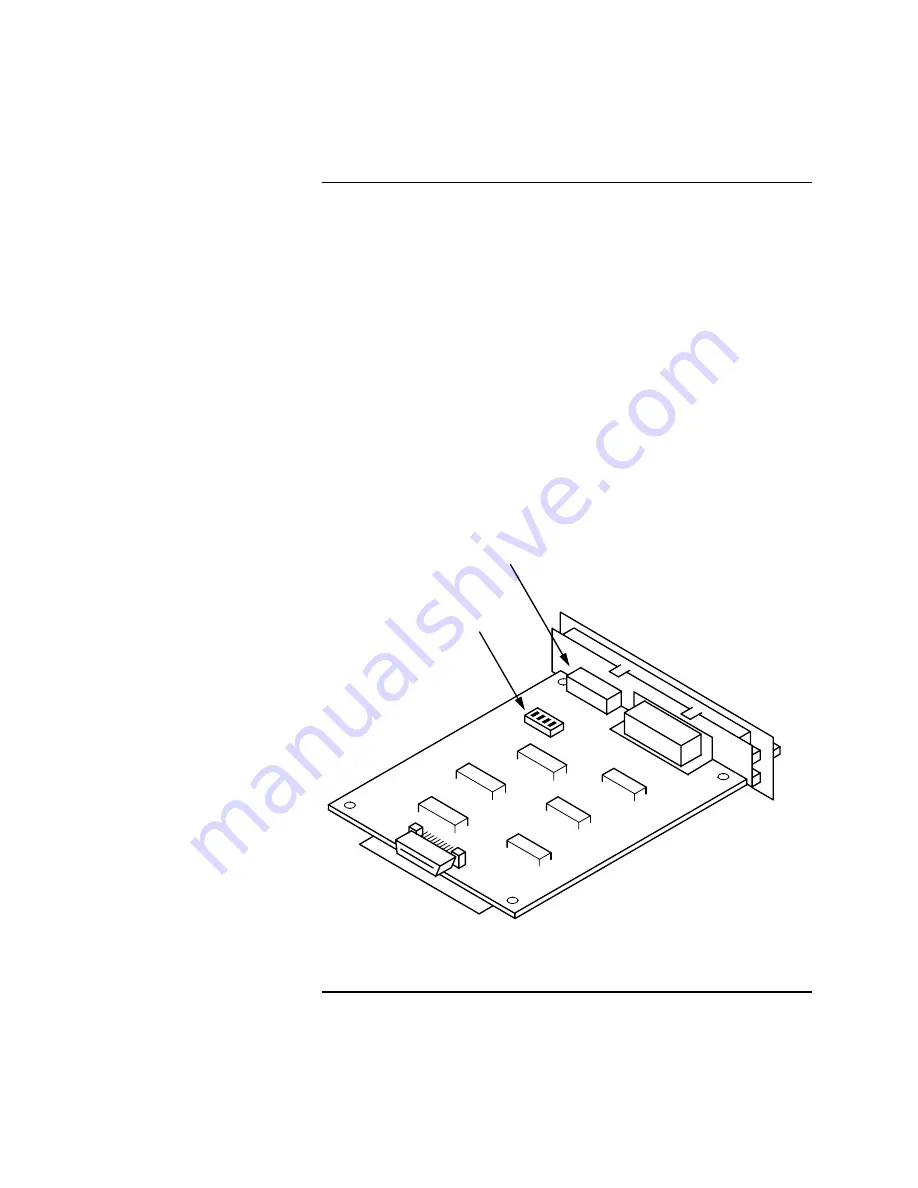
The serial interface card has two sets of DIP switches (see Figure 1).  You 
control interface operations by adjusting the switch settings.   
 

Notes:   


• 

You can access DIP Switch 1 and adjust settings as needed even after 
installing the interface card. 

• 

DIP Switch 2 is not readily accessible after installation.  Therefore, make 
any necessary adjustments to DIP Switch 2 before installing the serial 
interface card.


This section describes the DIP switch settings for operation with compatible Fire 
Alarm systems.  Refer to the 

Serial Interface Card

 manual (provided with the 

serial interface card) for detailed information on serial interface card installation. 
 

   DIP 

SWITCH 
      1

    DIP 
SWITCH 
      2


Figure 1.  Serial Interface Card DIP Switches 


Continued on next page 


Serial Interface DIP Switches 

Introduction 

firealarmresources.com

Содержание 4190-9013

Страница 1: ...tion against harmful interference when the equipment is operated in a commercial environment This equipment generates uses and can radiate radio frequency energy and if not installed and used in accor...

Страница 2: ...CR IBM 2390 Plus On Off A G M IBM 2390 Plus On Off Character table Standard model Italic PC 437 PC 850 PC 861 BRASCII Abicomp Roman 8 ISO Latin 1 PC 858 ISO 8859 15 All other models Italic PC 437 PC...

Страница 3: ...3 If you need to select a different language press the Font button until the Font lights indicate the language you want as described in the language selection instructions 4 Press the Tear Off Bin but...

Страница 4: ...talling the interface card DIP Switch 2 is not readily accessible after installation Therefore make any necessary adjustments to DIP Switch 2 before installing the serial interface card This section d...

Страница 5: ...F No parity 2120 4010 ON 1 4 Parity Check 2 ON For even parity 4020 4100 4120 OFF For odd or no parity 2120 4010 4120 GCC 4120 NPU ON 1 5 Baud Rate 1 ON for both 1200 baud 2120 4020 4100 4120 and 9600...

Страница 6: ...20 and 9600 baud 4010 4120 GCC 4120 NPU N A ON 2 2 Baud Rate 4 ON for 9600 baud rate 4010 4120 GCC 4120 NPU OFF for 1200 baud rate 2120 4020 4100 4120 OFF 2 3 Handshake DTR X on X off ON 2 4 RS 232D C...

Страница 7: ...nt is located directly above the parallel interface port on the rear panel of the printer see Figure 2 Note When connecting to a 4120 GCC system you have the option of using the parallel port If using...

Страница 8: ...BLK GRN WHT Use the standard parallel cable supplied with the printer the 733 937 harness is not used with the parallel interface Follow these steps 1 Disable the serial interface as follows a Loosen...

Страница 9: ...ion to the 4010 FACP 3 7 20 TO 4190 9013 PRINTER 3 7 20 2 RED NOT USED RECEIVE COMMON HANDSHAKE 2120 BMUX RS 232 CONNECTOR 733 937 HARNESS FURNISHED BLK GRN WHT Figure 5 Connecting to 2120 Multiplex S...

Страница 10: ...ain to confirm that you want to add an RS 232 card A message appears indicating that the system is configuring the card Press the EXIT key once to move back one menu level and then continue below with...

Страница 11: ...n printer Unused PRT40S Supervised 40 column printer PRT40U Unsupervised 40 column printer PRT80S Supervised 80 column printer 9 Use the arrow keys to move the bracket to the BAUD Parameter Use the NE...

Страница 12: ...rs indicating that the configuration has changed Move to the SAVE CFIG choice and press ENTER Another message appears asking you to confirm the Save operation Press ENTER to save the new CFIG Table 4...

Страница 13: ...937 harness is not used when connecting to the 5001 Nurse Call system Figure 7 illustrates the connection between the 4190 9013 printer and the 5001 CPU 2 6 7 TO 4190 9013 PRINTER RED 3 6 7 1 SHIELD...

Страница 14: ...tear off position Feeds continuous paper backward from the tear off position to the top of form position Selects a cut sheet feeder bin when the cut sheet feeder is installed and the release lever is...

Страница 15: ...ward to the stand by position in micro adjust mode Micro Adjust mode When you hold down the Pause button for three seconds the printer enters the micro adjust mode In this mode you can press the LF LL...

Страница 16: ...579 233 Rev A firealarmresources com...

Отзывы: