


BA_EA-KL²-DF(-K)_EN_13
www.simon-protec.com
Date: 20.08.2019
Issue: 1.3 / 08.2019
Page 7
Electrical connection
2. Electrical connection
2.1. Supply
The dimension of the power supply has to be suitable for this
actuator. Both voltage and current must fit the specifications
on the type label. Check the power supply before starting for
the first time, particularly noting the right wire cross-section.
Comply with the relevant directives with respect to minimum-
values for lead dimensioning.
Typical calculation (these are only approximate values and-
this is not an accurate calculation):
INFORMATION
Motor cable – notes on dimensioning (rule of thumbs):
wire cross-section [mm²] = single wire length [m]
x number of actuators
x power consumption
per actuator [A]
/ 73.
The national regulations are valid.
2.2. SINGLE connection
ATTENTION
When not in use, the wires “red” and “yellow” must be elec-
trically insulated.
The wires “red” and “yellow” may only be connected to-
gether for a RESET of the actuator.
¾
Connect wires according to connection diagram.
24V DC
blue
grey
brown
black
yellow
red
Tandem-Port
(electr. insulate)
Dry contact
“CLOSE”
(max. 28 V / 2.0 A)
OPEN: S = + O = - CLOSE: Pole-change
factory-provided
actuator
S
GND
O
T
NO1 NO2
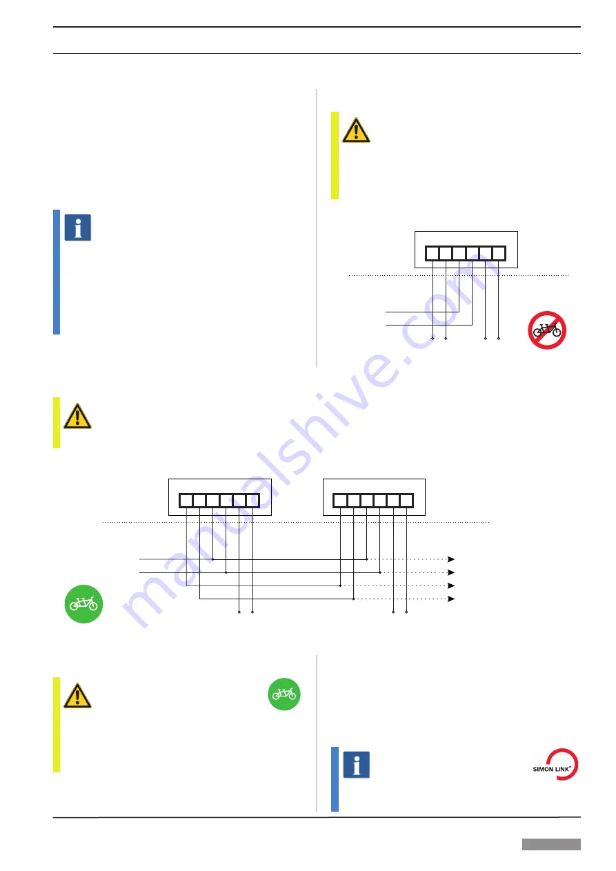
2.3. TANDEM operation
ATTENTION
Only for actuators mounted together on the same wing.
¾
Connect wires according to connection diagram.
24V DC
blue
grey
factory-provided
1. actuator
brown
black
yellow
red
Dry contact
“CLOSE”
(max. 28 V / 2.0 A)
blue
grey
2. actuator
brown
black
yellow
red
Dry contact
“CLOSE”
(max. 28 V / 2.0 A)
OPEN: S = + O = - CLOSE: Pole-change
S
GND
O
T
NO1 NO2
S
GND
O
T
NO1 NO2
2.4. TANDEM-Port
ATTENTION
Only a cut-off signal (e.g. overload cut-off) is forwarded
to the actuators connected in parallel. A line or function
monitoring of the actuators connected in parallel is not car-
ried out and thus does not lead to switching off the parallel
connected actuators.
2.5. Feedback – dry contact
The normally open contact (NO1, NO2) is switched when the
actuator is switched off in end position, the message depends
on the stroke and can be evaluated as “CLOSE / OPEN mes
-
sage”. By default, the dry contact is set to “CLOSE”. This sig-
nal contact is only active when the actuator is powered. It is
not a real end switch.
INFORMATION
The switching position (OPEN / CLOSE) of the contact
can be parametrised via SIMON LINK.


