3 DESCRIPTION
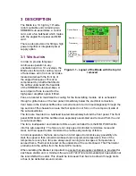
The Blade is a 1U high by 19” wide
rack-mountable unit containing two
SRM9000 sub-assemblies, a control
card, and a fan bulkhead which mates
with the angled front panel and MMI
card.
There is also provision for fitting a high
power amplifier or integrated power
supply option.
3.1 V
ENTILATION
In order to provide full-power
continuous operation in any
orientation and in a 1U envelope, the
Blade uses forced air-cooling. A pair
of fans draws air in from an air intake
located underneath the front lip of
the angled front panel. This air is
compressed by a baffle that directs
the airflow underneath the heatsink
of the SRM9000 sub assemblies. A
second pair of fans is used for the
high-power amplifier option if fitted.
Fans are located to maximise the cooling for the transmitting module. Air is exhausted
through a grilled area on the rear panel immediately below the electrical connectors.
Vent holes in the internal baffle allow a small amount of air to bleed diagonally through the
top section of the chassis to ensure that hot spots do not form on the component side of
the sub-assemblies.
The fans are mounted in a bulkhead located immediately behind the front panel. The front
panel, MMI board and fan bulkhead are separately assembled and removed from the unit
as sub-assemblies.
The fans, loudspeaker and indicator LEDs are all controlled from the MMI PCB that fits
into this sub-assembly. The fans are not only speed controlled to minimise noise and
wear, but their speed is also monitored to provide early warning of failure.
In normal operation, the fans are turned on to full speed to minimise any possibility of a
stall, the speed is then turned down based upon equipment temperature. Even if the
temperature is very low, fans are always kept running at a low speed. Temperature is
sensed from a Thermistor located on the underside of the control board. This Thermistor
protrudes into the airflow from the transmit PA module.
When installing the Blade it is important to ensure that adequate ventilation is provided for
each base station unit. A minimum free-area of 72cm
2
is recommended per base station at
the inlet AND at the outlet. This should be increased if air has to be drawn through ducts
or has to be deflected around corners.
Receiver
Transmitter
Control Board
Figure 3.1 - Layout of the Blade with the top lid
removed
High-power
Amplifier or
Integrated PSU
Option
Содержание Xfin Blade
Страница 10: ......
Страница 22: ......
Страница 35: ...XFIN BLADE SM TECHNICAL DESCRIPTION PAGE 35...
Страница 50: ......
Страница 58: ...PAGE 58 PRODUCT VARIANTS AND ACCESSORIES...
Страница 64: ...PAGE 64 SPARES...
Страница 72: ...PAGE 72 PROGRAMMER GUIDE...
Страница 75: ...XFIN BLADE SM CONTROL CARD BLOCK DIAGRAM PAGE 75 B CONTROL CARD BLOCK DIAGRAM...
Страница 76: ......


