Simex Simpact SLIK-73 Скачать руководство пользователя страница 19

User manual for universal counter with batching function SLIK-73

6.4. 


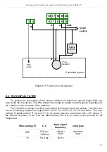
CONTROL OF THE RELAY OUTPUTS


The control of the object (measured signal) is realized via relay outputs. Front panel LEDs 
named „

R

” indicates the state of particular relay output.

Modes of the control can be changed depend on the values of parameters  

“SEtP”

,  

“timE”

“unit” 

and 

“modE”

 (additional number defines particular relay).


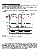
  Figure  6.5  presents   the   principle   of   relay   outputs   operation   for   example   values   of 

parameters.

Description:

A, B, C, D, E, F, G

- time points where result exceeds thresholds value,

t

A

 , t

C

 , t

E

 , t

G

- time while counter keeps result at least equal to threshold value

t

X


- time between subsequent exceeds of threshold value  (shorter than value of 

“timE”

parameter )

t

Z


- delay of relay reaction

Figure 6.5. Principle of relay outputs operation

Parameter  

“SEtP”

  defines  

threshold

  of   relay  

(trace:   a)

.   While   normal   operation   of 

counter, relay output can change its state to 

active

 only if

 counter value reaches (or exceeds) 

the 

threshold

 (for „up” counting 

points A, C, E, G )

. The 

active

 state of the relay (closed or 

open)   is   defined   by   parameter  

“modE”

.   Relay   R1   reacts   to   counter   value   changes 

immediately.   Other   relays   (if   available)   need   that   counter   value   be   same   or   greater   than 
particular 

threshold

 during at least 20 ms, to change the relay state.

19


“SEtP” 

parameter

(threshold value)

current 

counter 

value

displayed result

time

time

A

B

C

D

relay state

(

modE

 =

 on

timE

  =  0)

relay state

(

modE

 =

 on

timE

  >  0)

t

A

t

E

t

G

relay state

(

modE

 =

 oFF

timE

  =  0)

relay state

(

modE

 =

 oFF

timE

  >  0)

time

time

closed

open

a)

b)

c)

d)

e)

open

closed

open

open

closed

closed

“timE”

E

F

G

t

Z

t

C

“timE”

“timE”

t

X

time

“timE”

“timE”

“timE”

t

X

Содержание Simpact SLIK-73

Страница 1: ...unter with batching function family type SLIK 73 firmware version 7 03 or higher Read the user s manual carefully before starting to use the unit Producer reserves the right to implement changes witho...

Страница 2: ...N 22 7 2 1 Numeric parameters digit change mode 22 7 2 2 Numeric parameters slide change mode 22 7 2 3 Switch parameters LIST type 23 7 3 MENU DESCRIPTION 23 7 3 1 rELAy menu 24 7 3 2 Pr inP parameter...

Страница 3: ...ng to the application Incorrect configuration can cause defective operation which can lead to unit damage or an accident If in the case of a defect of unit operation there is a risk of a serious threa...

Страница 4: ...s by host and allows use of unit in advanced network systems Two counting inputs pulse inputs can operate in few different modes as two independent pulse inputs or single quadrature input Additional p...

Страница 5: ...ousing material Housing dimensions Mounting hole Assembly depth Panel thickness panel NORYL GFN2S E1 72 x 36 x 97 mm 66 5 x 32 5 mm min 102 mm max 5 mm Operating temperature Storage temperature Humidi...

Страница 6: ...st be immediately reported to the carrier Also write down the unit serial number on the housing and report the damage to the manufacturer Attached with the unit please find user s manual warranty asse...

Страница 7: ...igure 4 1 Mounting hole dimensions Figure 4 2 Installing of brackets and dimensions of connectors Figure 4 3 Minimum distances when assembly of a number of units 7 5 mm 92 mm 12 mm 10 mm 16 mm 8 5 mm...

Страница 8: ...operation Over tightening can lead to damaging the connections inside the units and breaking the thread In the case of the unit being fitted with separable clamps they should be inserted into appropri...

Страница 9: ...e unit should be as short as possible and the metal housing of the filter must be connected to the earthing with largest possible surface The cables connected to the filter output must not run in para...

Страница 10: ...ductive loads coils contactors power relays electromagnets motors etc it is required to use additional suppression circuit typically capacitor 47nF min 250VAC in series with 100R 5W resistor connected...

Страница 11: ...type outputs connection Construction of counter s inputs allows connecting of pulser with common earth Figure 4 10 a or common plus Figure 4 10 b without additional intermediary circuits sensor with N...

Страница 12: ...he internal components and shorten the fault free time of unit operation In cases where the unit gets dirty do not clean with solvents For cleaning use warm water with small amount of detergent or in...

Страница 13: ...parameter Enter to the sub menu Confirmation of changes made in parameter being edited Symbol used in the manual Functions Change of the present menu Modification of the parameter value Monitoring of...

Страница 14: ...epends on selected function There are available four functions addition of pulses from A and B inputs Funct A b subtraction of pulses from A and B inputs Funct A b quadrature counting with standard re...

Страница 15: ...k to the measurement mode If a thresholds values free access is enabled or thresholds and offset values free access is enabled see SECu menu user can change the value of particular parameter pressing...

Страница 16: ...no active A and B quAd 1 or quAd 4 other than dirEct any B and A quAd 1 or quAd 4 dirEct active Tab 6 1 Possible configurations while use device as a batcher Amount of poured fluid can be changed by p...

Страница 17: ...counting is providing of time periods of the pulses The filter can be set to blocking frequencies higher than 10 20 30 40 50 60 70 80 and 90Hz The time periods of stable states 0 t0 and 1 t1 of pulses...

Страница 18: ...60 Hz 70 7 2 ms 70 Hz 80 6 3 ms 80 Hz 90 5 6 ms 90 Hz Tab 6 2 Time periods t0 t1 depend on filtered frequency When the filter is turned off time periods t0 i t1 must be longer than 50 s see Figure 6...

Страница 19: ...timE parameter tZ delay of relay reaction Figure 6 5 Principle of relay outputs operation Parameter SEtP defines threshold of relay trace a While normal operation of counter relay output can change it...

Страница 20: ...t to 0 than relay stays in active state periods tA tC tE tG as long as counter value is equal or higher than threshold value traces b c If parameter timE is set to value different from 0 than relay st...

Страница 21: ...surement mode If a thresholds values free access is enabled or thresholds and offset values free access is enabled see SECu menu user can change the value of particular parameter pressing button ENTER...

Страница 22: ...ys or v causes change of current position flashing digit or the sign Short pressing of the ENTER button causes change of the position digit Press ENTER at least 2 seconds to accept the changes after t...

Страница 23: ...meter change of current flashing digit slide change of value acceleration deceleration direction change While editing switch parameter selection of switch parameter If numerical parameter is being edi...

Страница 24: ...nd timE When a particular LED lights its mean the relay is closed If parameter modE is set to modbuS value after power supply off and on again relays are open timE the time period of the relay active...

Страница 25: ...he RESET button on the front panel This operation must to be approved by ENTER button After zeroing counter displays value equals to oFFSEt parameter In this mode electronic reset is disabled nonE thi...

Страница 26: ...of inputs A and B as quadrature input with normal resolution it means that counter is incremented decremented by 1 every single quadrature cycle on inputs A and B qUAd 4 quadrature mode 4 This option...

Страница 27: ...99 If the value 0 is set then device responds to frames with address 255 FFh bAud this parameter determines RS 485 interface baud rate It can be set to one of 8 possible values 1 2 2 4 4 8 9 6 19 2 38...

Страница 28: ...availability of other parameters SEtCod user password 4 digits number If this parameter is set at value 0000 user password is turned off If the user do not remember his password the access to the men...

Страница 29: ...FFS value it is possible to use two different operation modes of quick view see Figure 7 1 Figure 7 2 Number of accessible parameters for viewing edition depends on device version Figure 7 1 Operation...

Страница 30: ...ter allows to change the edition mode of numerical parameters dig the change to by digit mode Slid slide change mode 7 3 12 dEFS parameter This setting allows to restore the factory settings of the de...

Страница 31: ...at least 2 seconds MENU ESC ENTER MENU ESC MENU ESC rELAy Measurement mode MENU ESC Pr inP MENU ESC rESEt ENTER MENU ESC ENTER ENTER MENU ESC SEtP modE unit Parameter edition See next page ENTER MENU...

Страница 32: ...ESC dEFS ENTER MENU ESC Parameter edition ENTER MENU ESC ENTER ENTER MENU ESC Addr bAud mbAccE mbtimE rESP See previous page MENU ESC SEt 4 digit special password entering 0 _ _ _ ENTER ENTER Default...

Страница 33: ...1 revolution 100 pulses Settings mul 50 div 100 oFFset 0 point 0 0 Example 3 counter SLIK 73 used in batcher function see Figure 6 2 6 3 Data flow meter 100 pulses L main valve flow valve 1 about 10...

Страница 34: ...0 to 115200 bits second Transmission protocol MODBUS RTU compatible The device parameters and display value are available via RS 485 interface as HOLDING type registers numeric values are given in U2...

Страница 35: ...ace only 13h Yes 0 1 ArESEt option main counter autoreset 0 oFF autoreset disabled 1 on enabled 14h Yes 0 9 FiLtEr option filtering rate 0 for input signal up to 10kHz frequency 1 up to 10Hz 2 up to 2...

Страница 36: ...ess 2Fh Yes 0 1 Edit parameter numerical parameters edit mode 0 dig mode 1 SLid mode 30h6 Yes see descr SEtP parameter in rELAy menu high word 31h6 Yes see descr SEtP parameter in rELAy menu low word...

Страница 37: ...rection 9 2 TRANSMISSION ERRORS DESCRIPTION If an error occurs while write or read of single register then the device sends an error code according to Modbus RTU specifications Error codes 01h illegal...

Страница 38: ...connected to the net BROADCAST message ADDR FUNC REG H L COUNT H L CRC L H 00 06 00 22 00 04 29 D2 DATA H 0 DATA L 4 new baud rate 19200 baud Device do not reply to BROADCAST type messages 4 Read of t...

Страница 39: ...TA H L CRC L H 01 06 00 11 00 01 18 0F The answer the same as the message ADDR FUNC REG H L DATA H L CRC L H 01 06 00 11 00 01 18 0F 7 Try to write illegal data value into baud rate register ADDR FUNC...

Страница 40: ...ngs menu PrESCA muL multiplier 1 26 div divider 1 26 oFFSEt Offset constant value added to the result to move the zero point of the current scale 0 26 Point Decimal point position 0 00 26 RS 485 inter...

Страница 41: ...User manual for universal counter with batching function SLIK 73 41...

Страница 42: ...User manual for universal counter with batching function SLIK 73 42...

Страница 43: ...User manual for universal counter with batching function SLIK 73 43...

Страница 44: ...SIMEX SIMEX Sp z o o ul Wielopole 7 PL 80 556 Gda sk Poland tel 48 58 762 07 77 fax 48 58 762 07 70 http www simex com pl e mail info simex com pl...

Отзывы: