mum pressure in
Table 3.
Turn the nut clockwise to increase or anti-clockwise to
decrease the burner pressure.
– Turn the main selector switch on and off a few times (with
the hot tap still open) and check that the pressure returns
to the correct (set) maximum value (as in
Table 3).
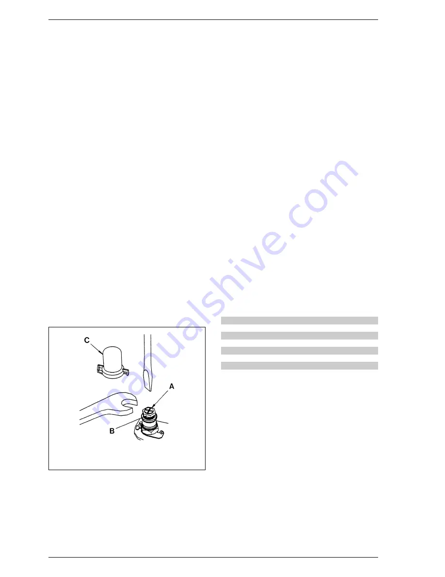
– Set the minimum burner pressure by first isolating the
electricity supply and disconnecting one of the modulat-
ing solenoid leads, then restore the electricity supply and
fully open a DHW tap to light the appliance at minimum
gas rate.
– Set the minimum pressure with reference to Tables 3 by
holding nut (B) in position with a 10 mm spanner and rotat-
ing the plastic screw (A) with a screwdriver until the correct
pressure is obtained. Turn the screw clockwise to increase
the pressure or anti-clockwise to decrease it. It is essential
that the max pressure has been set prior to adjusting the
minimum pressure. Check that the minimum pressure is
correctly set by turning on and off the D.H.W. inlet valve sev-
eral times and ensuring that the pressure returns to that
previously adjusted;
– Isolate the power supply, re-connect the modulation lead,
restore the power and re-check the maximum pressure,
then re-fit the plastic cover (1).
– Reduce the D.H.W. draw off rate to the minimum nec-
essary to maintain the burner alight by carefully adjusting
the D.H.W. Inlet valve and check that the burner pressure
decreases in response to D.H.W. temperature rise. Fully
open the inlet valve;
– Close the D.H.W. tap and ensure that the burner is extin-
guished and the pump stops.
– Adjus t t he Centr al Heating maximum pr essur e as
described in section 4.3, then complete the re-commis-
sioning as described in 4.4 and 4.5.
8.7
AIR PRESSURE SWITCH
– Remove the casing front panel and sealed chamber front
panel as described in section 5.1.
– Disconnect the pressure sensing pipe from the switch.
– Remove the switch (two screws) and fit the new one.
– Transfer the electrical connections one at a time (to ensure
that they are not incorrectly re-fitted) to the new switch.
– Re-assemble in reverse order referring to the wiring dia-
grams (section 7) if necessary. Ensure that the pressure
sensing lead is correctly connected to the low pressure
connection on the pressure switch (marked P2).
8.8
OVERHEAT THERMOSTAT
The overheat thermostat is situated on the flow pipe, below
the sealed chamber (11 fig. 24).
– Remove the casing front panel as described in section 5.1.
– Disconnect the two overheat thermostat wires.
– Unscrew the two limit thermostat fixing screws and
remove the thermostat.
– Replace the thermostat and spread heat sink compound
(supplied) over the base of the new one.
– Re-assemble in reverse order. (Polarity is immaterial).
8.9
THERMISTOR
The thermistor is placed over the main exchanger.
– Remove the casing front panel as described in section 5.1.
– Isolate the C.H. flow and return valves (19 - 18 fig. 2),
and drain the appliance through the drain plug (13
fig. 2).
– Pull off the electric connection, and unscrew the thermis-
tor from the exchanger.
– Replace the thermistor and re-assemble in reverse order.
Table 9 shows the resistance values (
Ω
) that are obtained
on the sensor as the temperature varies.
8.10
DRIVER PCB
– Remove the casing front panel as described in section 5.1.
– Open the control panel protecting cover by removing the
four fixing screw.
– Pull off the potentiometer knobs.
– Release the PCB (four screws), transfer all connections
onto the new PCB, and re-assemble in reverse order.
– Re-set the CH burner pressure as described in section 4.3.
8.11
PUMP MOTOR
– Remove the casing front panel as described in section 5.1.
– Unplug the electrical connection plug.
– Isolate the C.H. flow and return valves (19 - 18 fig. 2), and
drain the appliance through the drain plug (13 fig 2).
– Unscrew the four fixing screws on the motor.
– Replace the pump motor and re-assemble in reverse
order. If the new pump is fitted with a speed adjuster,
ensure that the speed is set to maximum.
23
Temperature (°C)
Resistance (
Ω
)
20
12,090
30
8,313
40
5,828
50
4,161
60
3,021
70
2,229
80
1,669
TABLE 9
KEY
A
Plastic screw
B
Nut
C
Sealing cap
Fig. 26
Содержание Murelle 25 BF
Страница 24: ...Format C installation and servicing instructions...
Страница 53: ...26...


