28
–
SAFETY THERMOSTAT ERROR
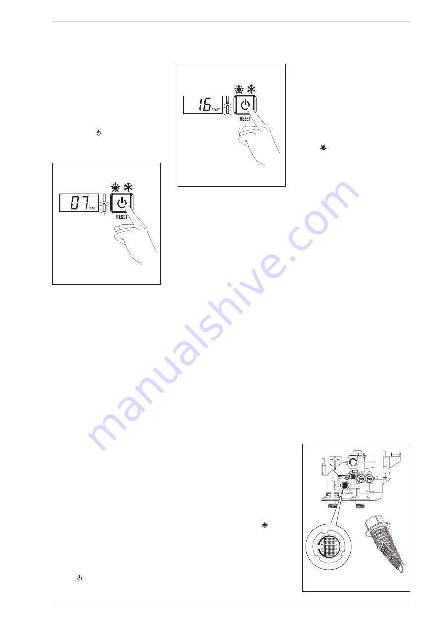
ALARM 07 (fig. 18/c)
If the C.H. sensor (SM1/SM2) exceeds
the 100°C the boiler will not ignite, the
display shows AL07 and the green LED
will stay lit. If the error persists for more
than one minute, the boiler will stop and
the red LED will illuminate.
Press the key
of the controls to start
up the boiler again.
–
FLAME DETECTION ERROR
ALARM 08
If a flame is detected when one should
not be present; the boiler will stop and
the display will show anomaly “AL 08”.
–
AUXILIARY SENSOR ERROR
ALARM 10
This error is not applicable to UK boilers,
check the setting of PAR 2.
–
MODULATOR ERROR ALARM 11
If the gas valve modulator coil becomes
disconnected or open circuit the display
will show "AL 11".
The boiler will function at minimum
power.
–
HEATING PROBE POSITIONING
ERROR SM1/SM2 “AL 16” (fig. 18/d)
If the heating probe sensor does not
detect a temperature rise within 10
seconds after a burner ignition, the bur-
ner will switch off, the display will show
AL16 and the green LED will stay lit.
If the error occurs three times within a
24hr period, the boiler will lockout, the
display continues to show AL16 and the
red LED illuminates.
Press
on the control panel to re-start
the boiler.
–
SENSOR ERROR “AL 17”
When the two sensitive elements of the
heating probe (SM1/SM2) dif fer to
each other by more than 16°C the boiler
does not operate and the display shows
error AL 17.
Replace the heating probe (SM1/SM2)
to restore operation.
4.6 COMMISSIONING
AND
ROUTINE SERVICE
Commissioning and servicing can only be
done by a qualified engineer.
4.6.1 Commissioning
PLEASE NOTE: The gas val ve f or t his
appliance has been checked, adjusted and
preset at the factory for operation on the
gas type defined on the appliance data
plate.
However it is advisable to check that the
gas valve is set correctly having first
checked:
- That the boiler has been installed in
accordance with these instructions.
- The integrity of the flue system and the
flue seals.
- The integrity of the boiler combustion cir-
cuit and all the relevant seals.
The following procedure should be done
after installation a gas purge and tight-
ness/drop test have been made.
Ensure that the auto air vent (13 fig. 3) is
opened, turn the electrical supply on.
With the boiler on standby fill the system
and pressurise to 1.5 bar (fig. 18/a).
Ensure that the pump has been manually
rotated.
Open the gas cock, press the “
mode
key” (fig. 10).
Check the operational (working) gas inlet
pressure.
Set up the boiler to operate at maximum
r at e as descr ibed in 4.4.1 (Chimney
sweep]).
With the boiler operating in the maximum
rate condition check that the operational
(working) gas pressure at the inlet test
point (see fig 14 item 3) is 21 mb +/- 2
mb.
Ensure that this inlet pressure can be
obtained with all other gas appliances in
the property working.
Check the setting of the gas valve, using
the procedure described in 4.2.2.and com-
pare the values to those shown in table 3.
Press “
mode key” (fig. 10).
Turn on a DHW tap fully (preferably the
bath tap), ensure that the boiler ignites.
Set the controls to the required values as
shown in the user guide.
Complete the Benchmark sheet enclosed
in this manual.
Explain controls and operation to the user.
Leave all documentation with the user.
Ensure that the boiler is registered with
gas Safe Register and Sime Ltd within 30
days of installation, and request that the
owner records the registration number in
the Benchmark checklist.
4.7
ROUTINE SERVICE
To comply with the conditions of any exten-
ded warranty offered and to ensure conti-
nued safe and efficient operation, the boiler
must be serviced at regular intervals at
least once a year.
It is the law that a Gas Safe Register regi-
stered engineer, must carry out any service
work.
4.7.1
Check / Clean Filter (fig. 19)
The filter is located within the connection of
the heat exchanger outlet pipe and the
DHW hydraulic assembly. Fig 19.
To check or clean the filter, turn off the gas
and electrical supplies to the boiler.
Close the flow and return isolation valves
and drain the boiler.
Protect the internal components of the boi-
ler fro accidental water spillage, then
Fig. 18/c
Fig. 18/d
Fig. 19
Содержание ECOMFORT PLUS 25 HE
Страница 3: ......
Страница 44: ...44 NOTES ...
Страница 45: ...45 NOTES ...
Страница 46: ...46 NOTES ...


