17
2.10
ELECTRICAL CONNECTION
The boiler is supplied with an electric cable.
Should this require replacement, it must be
purchased exclusively from SIME.
The electric power supply to the boiler must
be 230V - 50Hz single-phase through a 3
amp fused main switch, with at least 3 mm
spacing between contacts.
Respect the L and N polarities and the
earth connection.
NOTE: SIME declines all responsibility for
injury or damage to persons, animals or
property, resulting from the failure to pro-
vide for proper earthing of the appliance,
or incorrect connection of external con-
trols. Any fault or component failure due
to incorrect connection of external con-
trols is not covered in the warranty.
2.10.1
Climatic control option
The boiler is designed for connection to an
external temperature sensor, supplied on
request (code 8094101), which can auto-
matically regulate the temperature value of
the boiler output according to the external
temperature.
For installation, follow the instruction in the
package.
2.10.2 Use with different
electronic systems
Some examples are given below of boiler
systems combined with different electronic
systems.
Where necessary, the parameters to be
set in the boiler are given.
For the electrical connections to the boiler
refer to the diagrams (fig. 9 /9a).
Description of the letters indicating the
components shown on the system dia-
grams 1 to 3:
M
C.H. flow
R
C.H. return
SE
External temperature sensor
TA 1-2
Zone room thermostat
VZ 1-2 Zone valve
RL 1-2 Zone relay
Sl
Hydraulic separator
P 1-2
Zone pump
IP
Floor system
VM
Three-way mixer valve
TSB
Safety thermostat low
temperature
9
C
C33
11
10
3
1
1
3
3
7
3
12
12
12
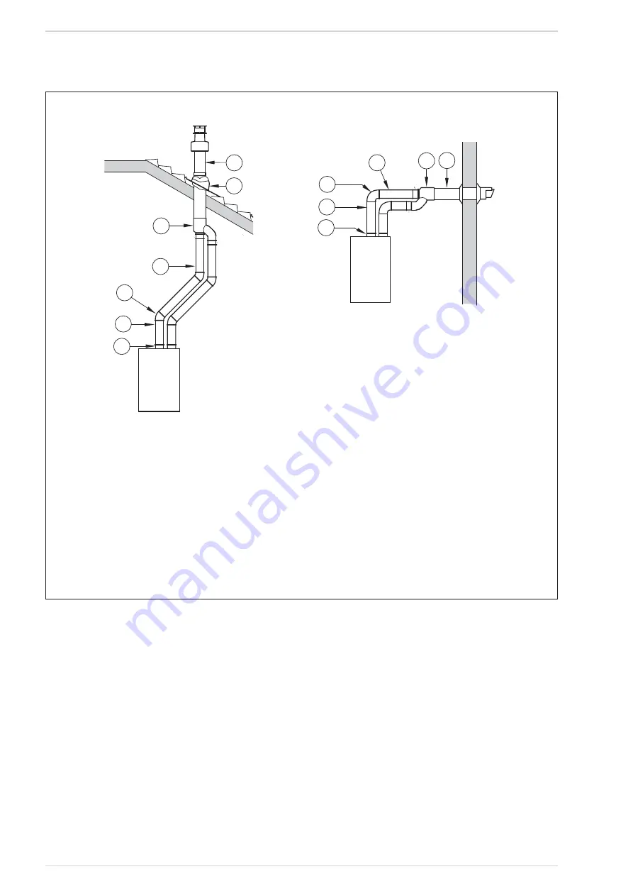
Fig. 8/a
C13
3
2
3
1
14
12
13
12
NOTE - HORIZONTAL TERMINALS MUST BE LEVEL
Before connecting accessories, it is always advisable to lubricate the internal
part of the gaskets with silicon products. Avoid using oils and greases.
LIST OF ø 80 ACCESSORIES
1 Separate pipe accessories code 8089912
3 a Extension L. 1000 code 8077351 (6 pz.), 8077351A (single)
3 b Extension L. 500 code 8077350 (6 pz.), 8077350A (single)
7 a Additional 45° MF curve code 8077451(6 pz.), 8077450A(single)
7 b Additional 90° MF curve code 8077450 (6 pz.), 8077451A(single)
9 Manifold, code 8091401
10 Tile for joint code 8091300
11 Terminal for roof exit L. 1381 code 8091212A
13 Union suction/exhaust code 8091401
14 Coaxial exhaust ø 80/125 L. 885 code 8096253A
C32
C12
Содержание ECOMFORT PLUS 25 HE
Страница 3: ......
Страница 44: ...44 NOTES ...
Страница 45: ...45 NOTES ...
Страница 46: ...46 NOTES ...


