background image

8.

Let the unit to remain in the CLEANING

mode for about 20 minutes then switch OFF the
machine.

9.

Flush out the cleaning solution from the

sump reservoir then pour onto the evaporator
cavity one or two liters of clean potable water with
the antibacteria solution P/N 26400002 to rinse
and sanitize the molds and the spray system.
If necessary remove the spary bar and nozzles to
clean them separately then refit them.

10. Set back the master switch to ON. The
water pump is again in operation to circulate the
water and the antibacterial solution in order to
rinse the entire water system.
Switch OFF the unit after approx. 10 minutes and
flush out the rinsing water from the sump reservoir.

11. To  rotate the timer so that the microswitches
reach the beginning of the defrost cycle (low part
of the cam) give power to the unit by the master
switch.
By doing so are energized the water pump and
the water inlet valve. In this way the incaming
water flow away to fill up the water tank.

12. When the water tank is filled up (water
flowing out from the drain) put the compressor
switch on I ON position to restart the machine in
the automatic mode.

13. Re-fit the evaporator cover and the unit
service panels.

14. At completion of the freezing and harvest
cycle make sure of proper texture and clearness
of the ice cubes and that, they do not have any
acid taste.

ATTENTION. In case the ice cubes are
cloudy, white and have an acid taste, melt
them immediately by pouring on them
some warm water.
This to prevent somebody from using
them.

15. Wipe clean and rinse the inner surfaces of
the storage bin.

REMEMBER. To prevent the accumulation
of undesirable bacteria it is necessary to
sanitize the interior of the storage bin with
an anti-algae disinfectant solution every
week
.

Page 13

2.

Wait till the end of defrost cycle then, shut

the unit OFF by means of its master switch.

3.

Scoop out all the ice cubes stored into the

bin in order to prevent them from being
contaminated with the cleaning solution then
flush out the water from the sump reservoir by
removing the overflow stand-pipe.

4.

Remove the plastic cup located on the

bottom of sump/freezing chamber to drain out all
water and scale deposits.

5.

Prepare the cleaning solution by diluting in

a plastic container two or three liters of warm
water (45

°÷

50

°

C) with a 0,2

÷

0,3 liters of Ice

Machine Cleaner PIN 00100901.

WARNING. The Ice Machine Cleaner
contains Phosphoric and Hydroxyacetic
acids. These compounds are corrosive
and may cause burns if swallowed, DO
NOT induce vomiting. Give large amounts
of water or milk. Call Physician
immediately. In case of external contact
flush with water. KEEP OUT OF THE
REACH OF CHILDREN

6.

Remove the evaporator cover then slowly

pour onto the evaporator platen the cleaning
solution. With the help of a brush dissolve the
most resistant and remote scale deposits in the
platen.

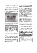
7.

Set the compressor switch on "0 - OFF"

position and give power to the unit by the master
switch (Fig.6).

NOTE. With the system in CLEANING mode
the water pump is the only component in
operation to circulate the cleaning solution in
the entire water system.

Содержание SD 125

Страница 1: ...SDN 25 SDN 30 SDN 35 SDN 45 SDN 65 SD 80 SD 125 SD 210 Automatic cubers Automatic Kegeleisbereiter 090091 05 REV 03 2008 ...

Страница 2: ...IEBSANLEITUNG 17 Starp up 4 Inbetriebnahme 17 Operational checks 4 Ueberprüfung im Betrieb 17 OPERATING PRINCIPLES 6 FUNKTIONSSYSTEME 19 Freezing Cycle 6 Gefrierprozess 19 Harvest Cycle 6 Abtauprozess 19 Control sequence 7 Steuersequenzen 20 Electrical sequence 7 Sequenz Elektrische Bestandteile 20 Components description 8 Komponentenbeschrieb 21 Service diagnosis 10 Fonktionsfehler 23 MAINTENANCE...

Страница 3: ...OLED MODELS LUFTKÜHLUNG WATER TEMPERATURE WASSERTEMPERATUR AMBIENT TEMPERATURE RAUMTEMPERATUR ICE PRODUCED PER 24 HRS EISWÜRFEL PRODUKTION IN 24 STD WATER COOLED MODELS WASSERKÜHLUNG WATER TEMPERATURE WASSERTEMPERATUR AMBIENT TEMPERATURE RAUMTEMPERATUR ICE PRODUCED PER 24 HRS EISWÜRFEL PRODUKTION IN 24 STD AIR COOLED MODELS LUFTKÜHLUNG WATER TEMPERATURE WASSERTEMPERATUR AMBIENT TEMPERATURE RAUMTEM...

Страница 4: ...DN 35 mm SDN 45 mm SDN 65 mm A 334 377 377 485 485 B 454 552 552 572 572 C 597 637 637 721 816 CORD SET ELEK KABEL Ø 20 WATER OUTLET WASSERABFLUSS G3 4 WATER INLET WASSEREINLAUF SDN 25 30 SDN 35 45 65 1 2 3 1 2 3 B A C B A C ...

Страница 5: ...1045 B 572 572 572 C 890 900 1050 CORD SET ELEK KABEL Ø 20 WATER OUTLET WASSERABFLUSS G3 4 WATER INLET WASSEREINLAUF G3 4 WATER OUTLET WASSERABFLUSS G3 4 WATER INLET WASSEREINLAUF Water cooled only Nur wassergekuhlt A B C SD 80 A B C SD 125 210 ...

Страница 6: ...r Air Water Air Water Air Water Air Water Air Water Air Water Kühlung Luft Wasser Luft Wasser Luft Wasser Luft Wasser Luft Wasser Luft Wasser Luft Wasser Luft Wasser Bin Capacity kg Speiker Kapazität kg 6 5 12 12 17 20 30 50 80 Net weight kg Netto Gewicht kg 28 33 40 45 48 61 94 131 Compressor power HP Kompressorleistung PS 1 5 1 5 1 5 1 4 3 8 1 2 1 1 5 Running amps Ampere 2 2 2 2 2 2 2 2 3 2 3 8 ...

Страница 7: ...WIRING DIAGRAM SCHALTUNGSSCHEMA 230 50 1 AIR WATER COOLED LUFT UND WASSERGEKÜHLT SDN 25 30 35 45 F ...

Страница 8: ...WIRING DIAGRAM SCHALTUNGSSCHEMA 230 50 1 AIR COOLED LUFTGEKÜHLT SDN 65 G ...

Страница 9: ...WIRING DIAGRAM SCHALTUNGSSCHEMA 230 50 1 WATER COOLED WASSERGEKÜHLT SDN 65 H ...

Страница 10: ...WIRING DIAGRAM SCHALTUNGSSCHEMA 230 50 1 AIR WATER COOLED LUFT UND WASSERGEKÜHLT SD 80 I ...

Страница 11: ...WIRING DIAGRAM SCHALTUNGSSCHEMA 230 50 1 AIR WATER COOLED LUFT UND WASSERGEKÜHLT SD 125 SD 210 L ...

Страница 12: ...A SD 80 125 210 AIR COOLED ONLY NUR SD 80 125 210 WASSERGEKÜHLTE VERSION FiG 1 FiG 1 FiG 3 FiG 5 FiG 6 FiG 2 FiG 4 1 FREEZING CYCLE 3 2 1 4 5 6 7 9 10 11 12 13 14 15 2 NO NC COM 3 2 4 NC NO COM 2 1 3 1 1 2 4 5 8 1 FREEZING CYCLE TIMING PHASE 3 2 1 4 5 6 7 9 10 11 12 13 14 15 2 NO NC COM 3 2 4 NC NO COM 2 1 3 1 1 2 4 5 8 1 DEFROST CYCLE 3 2 1 4 5 6 7 9 10 11 12 13 14 15 2 NO NC COM 3 2 4 NC NO COM ...

Страница 13: ... from the inside of the User Manual and fill in all parts including Model and Serial Number taken from the data plate Forward the completed self addressed registration card to SIMAG factory C LOCATION AND LEVELLING WARNING This Ice Maker is designed for indoorinstallationonly Extendedperiods of operation at temperature exceeding the following limitations will constitute misuse under the terms of t...

Страница 14: ...e with regular plumbing fitting and a shut off valve installed in an accessible position between the water supply line and the unit If water contains a high level of impurities it is advisable to consider the installation of an appropriate water filter or conditioner WATERSUPPLY WATERCOOLEDMODELS SD 80 125 210 The water cooled versions of SIMAG Ice Makers require two separate inlet water supplies ...

Страница 15: ...e factory 12 Has the owner been given the name and the phone number of the authorized SIMAG Service Agency serving him F FINAL CHECK LIST 1 Is the unit in a room where ambient temperatures are within a minimum of 10 C 50 F even in winter months 2 Is there at least a 15 cm 6 clearance around the unit for proper air circulation 3 Is the unit level IMPORTANT 4 Have all the electrical and plumbing con...

Страница 16: ...0 125 210 WATER PUMP FAN MOTOR in air cooled version D Check to see through the ice discharge opening that the spray system is correctly seated and that the water jets uniformely reach the interior of the inverted mold cups or the exterior of the evaporator tips also make sure that the plastic curtain is hanging freely and there is not excessive water spilling through it E Theicemakingprocesstakes...

Страница 17: ...mostat control bulb to test its shut off Fig 4 This should cause the ice maker to shut OFF after 30 seconds 1 minute at the most namely when the control bulb tempera ture drops to reach 1 C NOTE In case this test is performed during the freezing cycle the unit will shut OFF only at the end of the freeezing cycle and exactly when the timer switch actuators drop off into the cam slot Fig 5 Within mi...

Страница 18: ...0 air cooledtherefrigerantheadpressure inthecourse of the freezing cycle ranges between 8 10 bars SDN 65 8 9 5 bars SD 80 and 15 5 20 bars SD 125 210 being controlled by the hi pressure control When the discharge pressure rises up to a pre setvalue thepressurecontrolclosesitselectrical contacts suppling power to the FAN MOTOR As soon as the discharged refrigerant pressure drops the pressure contro...

Страница 19: ...adebyturning its adjusting screw located on front side With a clockwise rotation of the setting screw the thermostat cut IN temperature will be lowered longer freezing cycle thicker ice cube while with a counterclockwise rotation of the screw the Cut IN temperature rises shorter freezing cycle thiner ice cube Once completed the freezing cycle 2nd phase thesystemswitchesautomaticallyintothedefrost ...

Страница 20: ... cycle which in the circumstance is more likely a water filling cycle D TIMER Equippedwithtwomicroswitcheswhichplungers ride one timer cam the timer is located inside the control box The function of the timer begins when activated by the cube size control evap thermostat The large diameter lobe of its cam determines the 2nd freezing cycle portion length while the cam small diameter lobe determines...

Страница 21: ...PRESSURESWITCH BY HAND RESET Fastened directly onto the refrigerant liquid line and electrically connected upstream all other controls thissafetydeviceshut offtheicemakers when senses that the temperature at the liquid line has rised to the limit of 75 C 170 F or corresponding pressure H WATER SPRAY SYSTEM It consists of one spray bar with several spray nozzles on its extension Thewaterpumped issp...

Страница 22: ...h room temperature Move the unit in a more suitable place Cubes too small Freezing cycle too short Review setting of DIP SWITCH keys Capillary tube partially restricted Blow charge add new gas drier after evacuating system with vacuum pump Moisture in the system Same as above Shortage of water See remedies for shortage of water Shortage of refrigerant Check for leaks recharge Inoperative evaporato...

Страница 23: ... evacuating system with vacuu pump Hot gas solenoid valve leaking Replace valve Undercharge of refrigerant Charge to data plate indication Discharge head pressure too high See incorrect discharge pressure Poor harvest Restriction in incoming water line Check water valve strainer and flow control If necessary enlarge the flow control orifice Water inlet valve not opening Valve coil with open windin...

Страница 24: ...in line to be sure that drain line is open and clear 6 Check size condition and texture of ice cubes Perform adjustment of the evaporator thermostat or cube size control by turning its adjusting screw clockwise for a thicker ice cube and counterclockwise for a thiner one 7 Check the bin thermostat to test shut off Put a handfull of ice cubes in contact with its bulb This should cause the ice maker...

Страница 25: ...them some warm water This to prevent somebody from using them 15 Wipe clean and rinse the inner surfaces of the storage bin REMEMBER To prevent the accumulation of undesirable bacteria it is necessary to sanitize the interior of the storage bin with an anti algae disinfectant solution every week Page 13 2 Wait till the end of defrost cycle then shut the unit OFF by means of its master switch 3 Sco...

Страница 26: ...nde des Eisbehälters und die äußeren Oberflächen des Gerätes 8 Kontrollieren Sie die Daten auf dem Schild an der Rückseite des Rahmens und kontrollieren Sie ob die elektrische Versorgung mit der übereinstimmt die auf demselben Schild angegeben ist ACHTUNG Bei falscher elektrischer Versorgung erlischt automatisch Ihr Anrecht auf Garantie 9 Die Garantiekarte im Innern des Handbuches ausfüllen und ve...

Страница 27: ...r die Pumpenschale und eine die durch das mechanische Regulierungsventil zum Kühlkondensator verläuft Man benutzt auch für den Wasseranschluß des Kondensators den flexiblen Schlauch aus verstärktem Plastik welcher mit dem Gerät geliefertwirdundderaneingetrenntesSperrventil angeschlossen wird Wasserabfluß EswirdeinPlastikschlauchmiteinemInnendurch messer von 18 mm als Abflußleitung empfohlen Der Wa...

Страница 28: ...ber 40 C liegen darf 8 Wurden die Muttern die den Kompressor verankern kontrolliert Erlauben diese eine Schwingung auf den eigenen Halterungen 9 Wurden die Innenwände des Eisbehälters und die Außenwände des Gerätes gesäubert 10 WurdedasHandbuchmitdenAnweisungen abgeliefert und wurden dem Besitzer die notwendigen Instruktionen für die Funktion und dieperiodische WartungdesGerätesgegeben 11 Wurde di...

Страница 29: ...t ist und daß das Wasser gleichmäßig auf die umgedrehten Formen des Verdampfers gespritzt wird Kontrollieren daß der kleine Plastikvorhang korrektpositioniertwurdeunddenWasserauslauf durch seine Lamellen verhindert E Der Prozeß der Eisproduktion beginnt mit dem Wasser das ständig auf die umgedrehten Formen gespritzt wird und mit der ständig abnehmenden Temperatur des Verdampfers Während der ersten...

Страница 30: ...stellte Temperatur erreicht hat 1 C öffnet diese die KontakteundlöstsodasAbschaltendesGerätes aus ANMERKUNG Wenn dies Kontrolle während des Gefrierzyklus ausgeführt wird arbeitet das Gerät bis zum Ende des Zyklus weiter bis der Mikroschalter des Timers in den unteren Teil der Nocken ein tritt Beginn Abtauzyklus Fig 5 Wenn der Fühler vom Eis freigelegt wird beginnt die Maschine wieder mit ihren nor...

Страница 31: ...chreitet schließt der Druckwächter seine Kontakte und versorgt den Motor des Ventilators mit Elektrizität Fällt der Druck im Kondensator ab öffnet der Druckwächter seine elektrischen Kontakte und hält dadurch den Ventilator an Bei Versionen die mit Luft gekühlt werden SDN 25 45 funktioniert der Ventilator ständig und hält den Druck zwischen 8 10 bar Bei den Versionen von SDN 25 bis SDN 65 die mitW...

Страница 32: ...us länger Eiswürfel dicker währendimGegenuhrzeigersinndie Temperaturerhöhtwird Gefrierzykluskürzer Eiswürfel dünner Wenn die zweite Gefrierphase mit eingestellter Dauer beendet ist geht das Gerät direkt in die Abtauphase über Nachdem die Abtauphase beendet ist beginnt die Maschine automatisch mit einem neuen kompletten Zyklus SEQUENZ DER ELEKTRISCHEN BAUTEILE DienachstehendeTabellezeigt welcheKont...

Страница 33: ...st abgeschaltet wenn das Ende des Gefrierzyklus erreicht ist Auf diese Weise wird sicher gestellt daßinderZellevollgeformteEiswürfelvorhanden sindunddaßbeiWiedereinschaltendesGerätes Wasser zugeführt wird D TIMER Der Timer kontrolliert die Dauer der zweiten PhasedesGefrierzyklus obereTeilderNocken und die Dauer des Abtauzyklus unterer Teil der Nocken und besitzt zwei Mikroschalter die von einer No...

Страница 34: ...des Timers während des Abtauzyklus und Ladezyklus aktiviert Das Ventil öffnet dem Heißgas das vom Kompressor direkt durch die Serpentine des Verdampfers fließt um die Eiswürfel von den Formen zu lösen den Weg L VENTILATORMOTOR Luftgekühlte Versionen Der Ventilatormotor der bei den Versionen SDN 25 45 A und den Versionen SDN 65 SD 210A ständig funktioniert ist elektrisch mit dem Hochdruckwächter ve...

Страница 35: ...ieren Zu hohe Raumtemperatur Standort wechseln Zu kleine Eiswürfel Zu kurzer Gefrierzyklus Verdampferthermostat im Uhrzeigersinn drehen Kapillarrohr teilweise verstopft Entleeren und Feuchtigkeitsfilter erneuern und wieder auffüllen Feuchtigkeit im System Wie oben Wassermangel Siehe Wassermangel Zu wenig Kühlmittel Undichte Stellen suchen und nachfüllen Verdampferthermostat Thermostat ersetzen fun...

Страница 36: ...Wassereingangs ventils Gas kann vom System nicht Leeren und neu füllen kondensiert werden Zu wenig Luftzirkulation oder Aufstellungsort wechseln Raumtemperatur zu hoch Zu viel Kühlmittel Durch langsames Ablassen berichtigen Kapillarrohr teilweise verstopft Entleeren Feuchtigkeitsfilter ersetzen und füllen Undichtigkeit des Heißgasventils Ersetzen Zu wenig Kühlmittel Wie nach dem Schild nachfüllen ...

Страница 37: ...n den Kondensator mit Hilfe eines Staubsaugers oder einer Bürste nicht Metall 5 Die Wasserleitungen auf Undichtigkeiten kontrollieren Wasser in den Eisbehälter füllen um zu kontrollieren daß der Abfluß frei ist 6 Die Masse und den Aspekt der Eiswürfel kontrollieren Wenn notwendig dreht man die Regulierungsschraube des Thermostats im Uhrzeigersinn um die Masse zu vergrößern und im Gegenuhrzeigersin...

Страница 38: ...n wenn man lauwarmes Wasser in den Behälter schüttet um die ersten produzierten Eiswürfel aufzulösen 15 DieInnenwändedesEisbehältersabspülen ANMERKUNG Es wird daran erinnert daß die Innenwände des Behälters zur Vermeidung von Bakterienbildungen jede Woche mit einer Mischung aus Wasser und Desinfektionsmittel desinfiziert werden sollten D ANWEISUNGEN FÜR DIE REINIGUNG DES WASSERKREISLAUFES 1 Die vo...

Страница 39: ...et com sg I C E M A C H I N E S Certified ISO 9001 TOTAL QUALITY SIMAG via Risorgimento 4 20017 Mazzo di Rho MI Italy Tel 39 02 93900215 Commerciale Sales Dept Tel 39 02 93960357 Assistenza Service Dept Fax 39 02 93900226 Commerciale Sales Dept Fax 39 02 93960366 Assistenza Service Dept e mail sales simag it e mail service simag it www simag it ...

Страница 40: ...O BE SANITISED AND DE SCALED CLEAN THE MACHINE THOROUGHLY THEN FIRST DE SCALE AND AFTER PROPER WASHING AND RINSING DO THE SANITATION WARNING When using any chemical protection of hands and eyes should be worn NOTE De scaling is recommended every 6 months in average water hardness conditions while sanitizing should take place once a month Under extreme water hardness conditions we recommend to de s...

Страница 41: ...also the Bin Door 4 Wait until the end of defrost cycle then Switch OFF the machine at unit master switch 5 Scoop out all the ice cubes stored into the bin in order to prevent them from being contaminated with the cleaning solution 6 Flush out the water from the sump reservoir by removing the over flow stand pipe PAGE 2 6 ...

Страница 42: ...s are corrosive and may cause burns if swallowed DO NOT induce vomiting Give large amounts of water or milk Call Physician immediately In case of external contact flush with water KEEP OUT OF THE REACH OF CHILDREN 8 Remove the evaporator cover and 9 slowly pour onto the evaporator platen the cleaning solution 10 With help of a brush dissolve the most resistant and remote scale deposits in the plat...

Страница 43: ...the entire water system 13 Let the unit to remain in the CLEANING MODE for about 20 minutes and switch OFF the machine 14 Flush out the cleaning solution from the sump reservoir then 15 pour onto the evaporator cavity one or two liters of clean potable water with cc 2 antibacteria solution part number 264000 02 to rinse and sanitize the molds and the spray system ON PAGE 4 6 ...

Страница 44: ...l solution in order to rinse the entire water system 18 After approx 10 minutes Switch OFF the unit and 19 fush out the rising water from the sump reservoir 20 Rotate the Timer so that the microswitches reach the beginning of the defrost cycle low part of the cam then give power to the unit at master switch By doing so the water inlet valve is in this way the incaming water fill up the water tank ...

Страница 45: ...ure and clearness of the ice cubes as well as that they do not have any acid taste ATTENTION In case the ice cubes are cloudy white and have acid taste melt them immediately by pouring on them some warm water This to prevent somebody from using them 24 Wipe clean and rinse the inner surfaces of the storage bin REMEMBER To prevent the accumulation of undesirable bacteria it is necessary to SANITIZE...

Отзывы: