OPERATING
INSTRUCTIONS
START UP
After having correctly installed the ice maker and
completed the plumbing and electrical
connections, perform the following “Start-up”
procedure.
A.
Put the icemaker in operation by moving the
unit master switch, located on the cabinet front,
to the ON position.
NOTE. The icemaker control is factory set
with the timer microswitches actuators
dropped off into the initial point of the cam
slot. This setting position allows a proper
water filling.
The unit starts operating in the “defrost cycle”
with the following components being activated:
THE WATER INLET SOLENOID VALVE
THE HOT GAS SOLENOID VALVE
THE CONTACTOR COIL (SD 80-125-210)
THE FAN MOTOR (only SDN 25
÷
45) air cooled
THE COMPRESSOR
THE TIMER MOTOR
B.
During the water filling operation, check to
see that the incoming water dribblers, through
the evaporator platen dribbler holes, down into
the sump reservoir to fill it up and also that the
incoming surplus of water flows out through the
overflow pipe into the drain line.
NOTE. If, in the defrost cycle length, the
machine sump reservoir does not get filled
with water up to the rim of the overflow pipe,
remove the front panel and rotate the shaft of
the timer so to cause the dropping of the two
microswitches actuators into the beginning
of the cam slot and check for:
1. The water pressure of the water supply
line, it must be at least 1 bar (14 psig)
Minimum (Max 5 bar-70 psig).
2. The filtering device installed in the water
line that may reduce the water pressure
below the Minimum value of 1 bar (14 psig).
3. Any clogging situation in the water circuit
like the inlet water strainer and/or the flow
control.
OPERATIONAL CHECKS
C.
At completion of the water filling phase the
unit initiate automatically the first freezing cycle
with the start up of (Fig.1):
COMPRESSOR
CONTACTOR COIL (SD 80-125-210)
WATER PUMP
FAN MOTOR (in air cooled version)
D.
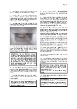
Check to see through the ice discharge
opening that the spray system is correctly seated
and that the water jets uniformely reach the
interior of the inverted mold cups or the exterior
of the evaporator tips; also make sure that the
plastic curtain is hanging freely and there is not
excessive water spilling through it.
E.
The ice making process takes place thereby,
with the water sprayed into the molds or onto the
tips that gets gradually refrigerated by the heat
exchange with the refrigerant flowing into the
evaporator serpentine.
During the first portion of the freezing cycle, the
timer assy is standing-by with its microswitches
actuators resting on the raised cam profile
(position that correspond to the end of the defrost
cycle).
F.
Then, as the cube size control cut-in point is
reached by the evaporator temperature the control
of the cycle is passed to the timer assy. Whose
raised cam slowly rotates to continue the freezing
cycle (2nd phase) up to its completition.
The components in operation during this 2nd
phase of the cycle are (Fig.2):
COMPRESSOR
CONTACTOR COIL (SD 80-125-210)
WATER PUMP
FAN MOTOR (in air cooled version)
TIMER MOTOR
G.
After about 18
÷
20 minutes from the
beginning of the freezing cycle, in an hypothetic
ambient temperature of 21
°
C, the defrost cycle
takes place with the hot gas and the water inlet
valves being simoultaneously activated.
The electrical components in operation are (Fig.3):
COMPRESSOR
CONTACTOR COIL (SD 80-125-210)
WATER INLET SOLENOID VALVE
HOT GAS VALVE
TIMER MOTOR
FAN MOTOR (only SDN 25
÷
45) air cooled
H.
Check, during the defrost cycle, that the
incoming water flows correctly into the sump
reservoir in order to refill it and that the surplus
overflows through the overflow drain tube.
I.
Check the texture of ice cubes just released.
They have to be of the right size with a thickness
of about 7
÷
8 mm.
If the ice cubes have not the correct size, wait for
a second harvest before attempting any
adjustment by setting the cube size control.
Page 4
Содержание SD 125
Страница 7: ...WIRING DIAGRAM SCHALTUNGSSCHEMA 230 50 1 AIR WATER COOLED LUFT UND WASSERGEKÜHLT SDN 25 30 35 45 F ...
Страница 8: ...WIRING DIAGRAM SCHALTUNGSSCHEMA 230 50 1 AIR COOLED LUFTGEKÜHLT SDN 65 G ...
Страница 9: ...WIRING DIAGRAM SCHALTUNGSSCHEMA 230 50 1 WATER COOLED WASSERGEKÜHLT SDN 65 H ...
Страница 10: ...WIRING DIAGRAM SCHALTUNGSSCHEMA 230 50 1 AIR WATER COOLED LUFT UND WASSERGEKÜHLT SD 80 I ...
Страница 11: ...WIRING DIAGRAM SCHALTUNGSSCHEMA 230 50 1 AIR WATER COOLED LUFT UND WASSERGEKÜHLT SD 125 SD 210 L ...


