


2. Quick Start Demonstration
A video showing the quick-start demonstration is available at
http://www.silabs.com/zigbeesmartoutlet
.
1. Set up an HA 1.2 ZigBee gateway.
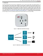
2. Supply power to the ZigBee Smart Outlet.
a. Ensure the reference design is connected to a main power source. Note that the outlet power supply is rated to 240 VAC,
however, the the North American plug is rated to 120 VAC.
b. The reference design is powered when the green LED momentarily flashes at least once.
3. Connect the ZigBee Smart Outlet to the ZigBee network.
a. Follow the directions provided with the ZigBee gateway to enable the smart outlet reference design to join its ZigBee network.
b. Depress and hold external front button for more than three seconds, then release to begin the network join procedure.
c. The outlet has joined the ZigBee network when the green LED blinks six times.
4. Demonstrate ZigBee Smart Outlet functionality.
a. Send an “on” command from the gateway to the smart outlet. This should cause an audible click to occur (from the internal
relay), the red LED will blink once and power will be applied to the front female plug outlet.
b. Send an “off” command from the gateway to the smart outlet. This should cause an audible click to occur (from the internal
relay), the red LED will blink once and power will be removed to the front female plug outlet.
c. To manually provide or remove power from the female front outlet, hold the front button for more than half a second, but less
than two seconds to toggle between states.
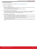
d. If supported by the gateway, the on-board sensors on the reference design can be viewed by the user interface of the gate-
way.
UG171: ZigBee
®
Smart Outlet Reference Design (RD-0051-0201) Kit User's Guide
Quick Start Demonstration
silabs.com
| Smart. Connected. Energy-friendly.
Rev. 0.1 | 2


