


MS100/1
Installation English
MS100/1 · Date
27.04.2018 · Art.
No.
82106 · Mod.
status
118/18
18
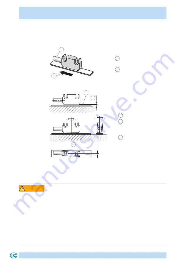
2. Use two M3 screws to fix the magnetic sensor design L via the ø3.1 mm
through holes (fastening torque = 1 Nm).
Use two M2.5 screws to fix the magnetic sensor design B-TR via the two
threaded holes (fastening torque = 1 Nm).
1
Travel direction sensor,
counting direction negative
2
Direction of outgoing cable
Fig. 6: Definition of counting direction
1
Active side magnetic tape
2
Admissible deviation of
tape/sensor
≤0.4 mm
3
Maximum alignment error
Fig. 7: Assemblage sensor / magnetic tape, gap measure, tolerances
<1°
<3°
<3°
4.4 Electrical installation
Destruction of parts of equipment and loss of regulation control
`
All lines for connecting the magnetic sensor must be shielded.
`
Never wire or disconnect electrical connections while they are live.
`
Perform wiring work in the de-energized state only.
`
Use strands with suitable ferrules.
`
Wiring to the screen and ground (0 V) must be secured to a good
point. Ensure that the connection of the screen and earth is made to a
large surface area with a sound connection to minimize impedance.
`
Check all lines and plug connections before switching on the device.
`
Switch on operating voltage together with the downstream electronic
unit (e. g., control unit).
WARNING
Содержание MS100/1
Страница 22: ...MS100 1 22 ...
Страница 23: ...MS100 1 23 ...