


MSK500/1
+MB500/1+MR500
Datum 12.05.2015
Art.Nr. 81413
Änd. Stand 87/15
9
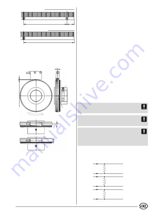
Fig. 6: Definition of the counting direction with ma-
gnetic strip and assemblage sensor/magnetic ring,
gap measure, toleran ces
Periodical reference point
Position of the reference point R = as
stated in the delivery documentation
Magnetic poles -
schema
Unique reference point
Position of the reference point E = as stated
in the delivery documentation; min. 0.05 m
Fig. 7: Definition of the counting direction with ma-
gnetic ring and assemblage sensor/magnetic ring, gap
measure, tolerances
Direction of outgoing cable
0.
1 ... 2 mm wit
hout r
efer
ence point
0.
1 ... 1.5 mm wit
h r
efer
ence point
<3°
Signal
A before B
U n d e r c u t
at the solid
shaft for
tread plug is
recommen-
ded
reference
point
Direction or rotation of
magnetic ring
Admissable deviation
middle of tape/sensor:
without ref. point ±2 mm
with ref. point ±0.5 mm
<3°
RADIAL
application
MSK500/1 with MR500:
lines!
Suitable wiring layout and choice of cable
can minimise the effects of interference (e. g. in-
terference caused by SMPS, motors, cyclic controls
and contactors).
Necessary measures
• Only screened cable should be used. Wire cross
section is to be at least 0.14 mm²; max. 0.5 mm².
• Wiring to the screen and ground (0 V) must be se-
cured to a good point. Ensure that the connection of
the screen and earth is made to a large surface area
with a sound connection to minimise impedance.
• The system should be positioned well away from
cables with interference; if necessary
a protective
screen or metal housing
must be provided. The
running of wiring parallel to the mains supply
should be avoided.
• Contactor coils must be linked with spark sup-
pression.
Supply voltage
The voltages depend on the sensor designs; they
are to be taken from the delivery documentation
and the identification plate.
e. g.:
24 V DC ±20 %
Attention!
When connecting sensor and follower
electronics, please do not exceed the max. admis-
sable cable length.
Note:
In case of operating voltage 24 V DC and out-
put circuit LD we recommend use of terminal resi-
stors ≥470 Ohm in order to avoid thermic overload.
Note:
With a 4-increment wide (= 360°) index/
reference signal, index/reference signal interpre-
tation can be made after the 5th counting step (in-
crement) only. Corresponding time delay has to be
considered when power is switched on.
4.1 Connection note acc. to RS422 standard
Please provide the channels with a 120 Ohm termi-
nating resistor.
4. Electrical connection
• Wiring must only be carried out with power off!
• Check all lines and connections before switching
on the equipment!
Interference and distortion
All connections are protected against the effects
of interference.
The location should be selected
to ensure that no capacitive or inductive inter-
ferences can affect the sensor or the connection