Siko MB500/1 Скачать руководство пользователя страница 11

MSK500/1

+MB500/1+MR500


     Datum 12.05.2015 

Art.Nr. 81413 

Änd. Stand 87/15 

11

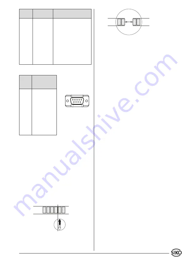
viewing side = plug-in side

plug pin

Fig. 10: Determination of the pole position. Cutting 
the magnetic strip

Fig. 11: Determination of the pole position. Joining 
the magnetic strip

 

Signal

inverted

inverted with

reference signal

A

Pin 1

Pin 1

B

2

2

I, R

- - -

3

+UB

4

4

GND

5

5

A/

6

6

B/

7

7

I/, R/

- - -

8

nc

3, 8, 9

9

E8E:

 Connection with 9 pole D-SUB plug.

Signal inverted with

reference 

signal

nc

PIN 1

I/, R/

2

B/

3

A

4

GND

5

+UB

6

I, R

7

B

8

A/

9

5. Joining magnetic strips together

For some applications it may be necessary to extend 
the magnetic strip. The magnetic strip can be cut 
and rejoined using standard tools.

But however carefully this is done the accuracy of 
the strip at the join will be impaired (error of at 
least 0.1 ... 0.2 mm).

The following tools / accessories are required:

•  magnet magnifier, magnetic foil or metal dust
•  rule or suitable tool
•  compass needle

Steps

•  If there is a cover strip, this is to be removed first.
•  To determine the pole division either use metal 

dust, a magnet magnifier or magnetic foil.

•  If necessary, use a compass needle to determine the 

location of the poles on the magnetic strip (fig. 10).

•  Use a rule and a sharp knife to cut the magnetic 

strip at a right angle. Then also cut the carrier 
strip accordingly.

•  Previous steps are to be repeated with the other 

part of strip.

•  Check  polarity  before  joining  the  two  parts.       

Both ends must attract each other (if necessary, 
use compass needle). In case both ends have the 
same polarity, shorten one end by a half pole 
division (fig. 11).

•  Join the two ends closely together and add the 

cover strip.

6. Maintenance

We recommend cleaning the magnetic strip's sur-
face from time to time with a soft rag. This avoids 
dirt (dust, chips, humidity ...) sticking to the strip.

7.  Trouble shooting

Below are some typical errors which may occur duri-
ng installation and operation:

•  Magnetic strip incorrectly mounted (active sur-

face must be mounted towards the sensor) (see 
chapter 3.1).

•  Use of foreign protective strip. Must always be 

non-magnetic.

•  Sensor not or incorrectly connected (pin connec-

tion, see chapter 4.2).

•  Tolerance for the gap between magnetic sensor 

and magnetic strip not observed over the 

total


travel distance. Sensor touches strip (see fig. 6+7).

•  Cable squeezed / interrupted / cut by sharp edges.
•  Sensor's active side not mounted towards the 

magnetic strip (see fig. 6+7).

•  Sensor has not been aligned according to fig. 6+7.

Содержание MB500/1

Страница 1: ... Montagefläche bzw der zu messenden Strecke erfolgen Welligkeiten ver schlechtern immer die Messgenauigkeit Überall wo aufgrund unzureichender Befestigungsmöglichkeiten keine geeignete Montage des Magnetbandes möglich ist kann das Magnetband in eine als Zubehör lieferbare Profilschiene z B Typ PS oder PS1 montiert werden Dadurch entsteht eine kompakte Ma gnetbandeinheit Aus technischen Gründen mus...

Страница 2: ...s möglichst kraft und spannungsfrei montiert werden Eventuell erforderliche Belastungen sind am Metallflansch aufzubringen Schläge auf den Magnetring sind zu vermeiden Ein Wellenfreistich entsprechend Abb 7 wird empfohlen 3 3 Montage Magnetsensor MSK500 1 Der Magnetsensor MSK500 1 kann durch Verwen dung von 2 Schrauben M3 über die ø3 5 mm Durch gangslöcher befestigt werden Es wird empfohlen die be...

Страница 3: ...leich muss großflächig niederimpedant erfolgen DasSystemmussinmöglichstgroßemAbstandvon Leitungen eingebaut werden die mit Störungen belastetsind ggfs sindzusätzlicheMaßnahmen wie Schirmbleche oder metallisierte Gehäuse vorzusehen Leitungsführungen parallel zu Ener gieleitungen vermeiden Schützspulen müssen mit Funkenlöschgliedern beschaltet sein Spannungsversorgung Die Spannungswerte sind abhängi...

Страница 4: ...en und auf Pos 3 stecken Schlitz und Nut Pos 3 und 4 müssen deckungsgleich sein 7 Pos 6 an Pos 5 drücken überstehenden Schirm abschneiden 8 Pos 2 und 7 aufschieben und verschrauben 9 Pos 8inPos 9stecken beidesinPos 7schieben 10 Pos 10 mit Pos 7 verschrauben 11 Pos 1 in Pos 2 schieben 4 2 Anschlussarten Anschlussbelegung E1 Anschluss mit offenen Kabelenden Achtung Verzinnte Litzen dürfen nicht in V...

Страница 5: ...n halben Polabstand kürzen Abb 11 BeideBänderstoßendmontierenundAbdeckband aufkleben 6 Wartung Die Oberfläche des Magnetbandes ist bei starker Verschmutzung durch Staub Späne Feuchtigkeit usw von Zeit zu Zeit mit einem weichen Lappen zu reinigen 7 Fehlerbehandlung Typische Fehler die bei Anbau und Betrieb auftre ten Das Magnetband wurde falsch montiert aktive Seite nach unten siehe Kapitel 3 1 Zum...

Страница 6: ...os sen Pinbelegung Kapitel 4 2 Die Abstandstoleranz zwischen Sensor und Ma gnetband Magnetring wurde nicht eingehalten beim Band über die gesamte Messstrecke der Sensor streift auf dem Magnetrin Abb 6 7 Kabelunterbrechung Abtrennung durch scharfe Kanten Quetschung Der Sensor ist mit der aktiven Seite vom Band abgewandt montiert Abb 6 7 Der Sensor wurde nicht entsprechend Abb 6 7 ausgerichtet ...

Страница 7: ...d to measuring inac curacies For applications which do not allow properly glueing of the magnetic strip it can be inserted into a profile rail accessory e g rail type PS or PS1 thus forming a compact mounting unit For technical reasons the strip should be approx 100 mm longer than the actual measuring distance Attention To guarantee optimal adhesion oil grease dust etc must be removed by using cle...

Страница 8: ...irectioncanbereversed in the electronic interpretation e g in SIKO s magnetic strip displays Attention The tolerance and gap measures must be observed over the whole measuring length LINEAR application MSK500 1 with MB500 1 Attention Do not expose the system to magnetic fields Any direct contact of the magnetic strip with magnetic fields e g adhesive magnets or other permanent magnets is to be avo...

Страница 9: ...ionof thescreenandearthismadetoalargesurfacearea with a sound connection to minimise impedance The system should be positioned well away from cableswithinterference ifnecessaryaprotective screen or metal housing must be provided The running of wiring parallel to the mains supply should be avoided Contactor coils must be linked with spark sup pression Supply voltage The voltages depend on the senso...

Страница 10: ...res 6 Open spacer part 4 and put it over ferrules squeeze and push it onto part 3 Slot and keyway of parts 3 and 4 must align 7 Press parts 6 and 5 together cut prodruding screening 8 Push parts 2 and 7 together and screw 9 Push part 8 into part 9 and slide both parts into part 7 10 Screw parts 10 and 7 together 11 Push part 1 into part 2 E6 Connection with plug pin and socket contact Plug mountin...

Страница 11: ...letodeterminethe locationofthepolesonthemagneticstrip fig 10 Use a rule and a sharp knife to cut the magnetic strip at a right angle Then also cut the carrier strip accordingly Previous steps are to be repeated with the other part of strip Check polarity before joining the two parts Both ends must attract each other if necessary use compass needle In case both ends have the same polarity shorten o...

Страница 12: ... 87 15 SIKO GmbH Werk Factory Weihermattenweg 2 79256 Buchenbach Unteribental Postanschrift Postal address Postfach 1106 79195 Kirchzarten Telefon Phone 49 7661 394 0 Telefax Fax 49 7661 394 388 E Mail info siko de Internet www siko global com Service support siko de ...

Отзывы: