


IF09I/1
Datum 03.09.2008
Art.Nr. 80931
Änd. Stand 324/08
9
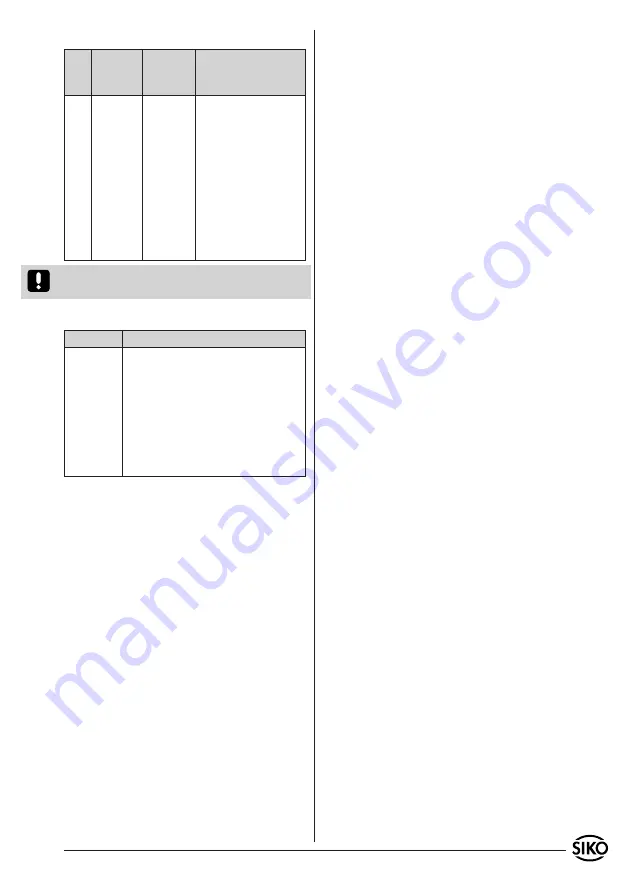
Interfaces /Sensor (AP09)
Pin
X2
Interbus
In
X3
Interbus
Out
X4
Sensor
1
DO
DO
+24V
(Encoder supply,
max. 600mA)
2
DI
DI
- - -
3
GND1
GND
DÜA (RS485)
4
- - -
- - -
- - -
5
- - -
Vcc
GND
6
/DO
/DO
- - -
7
/DI
/DI
- - -
8
- - -
- - -
DÜB (RS485)
9
- - -
RBST
- - -
Caution!
GND1, GND are galvanically isolated and
must not be interconnected!
X1 Power supply
Pin
Description
2
GND
3
+UB 24VDC
optionally
1
or
Grounding line PE
(For noise suppressi-
on PE should be connected with a short cable
(2,5mm
2
))
4
Grounding line PE
(For noise suppressi-
on PE should be connected with a short cable
(4mm
2
))
Shield connection
The DSUB casing of the incoming remote bus in-
terface is internally connected to the PE connec-
tion by means of a RC combination (1MW||15nF)
(to avoid equalizing currents via cable screen).
The DSUB connectors of the forwarding remote bus
interface and the encoder connection are directly
connected to PE.
6. Functional description
Immediately after applying supply voltage, the
IF09I/1 is in the RESET state for approx. 1,5s; the
rotary encoders linked to the encoder connection
are, however, supplied with voltage so that they
can be initialized.
IF09I/1 with standard protocol S3/00
After reset time expiration the POWER-ON-LED co-
mes on and signals readiness for working. Then,
within the following 2,5s, it is checked whether a
device is connected to the IF09I/1's sensor input.
During this period the yellow LED "SENSOR CHECK"
is on. If there is a connection, the LED will come
on permanently. The Interbus protocol chip will
then be initialized by the ID-code 37 Hex with a
data width of 4 Byte (= 2 data words).
If no device has been found / connected, the
IF09/1 will make after appprox. 2,5s another
attempt for communication and repeat this until
a device is connected or supply voltage switched
off. An Interbus master connected during this in-
itialization procedure recognizes any connected
device as ID-code 38
Hex
(remote bus participant
with µP-Not-Ready-ID-Code).
After this initialization period the AEA SA02 peri-
odically reads out its position value and transmits
it to the Interbus interface. The AEA's cycle time is
at the best 790µs (max. approx. 1,2ms).
IF09I/1 with SIKONETZ4 Protocol S3/07
After the end of the reset period the POWER-ON
LED is lit and indicates the ready state. During
the following approx. 2,5s the number of rotary
encoders connected to the encoder interface is de-
termined. During this period the yellow "SENSOR
CHECK" LED will blink with a pulse/interval ratio
of 1:1. The detected number of rotary encoders is
afterwards communi-cated to the user by n-time
blinking of the "SENSOR CHECK" LED with a pul-
se/interval ratio of 1:4, where n = the number of
connected rotary encoders.
After this initialization procedure the rotary en-
coders are periodically read out and the position
values transferred to the Interbus interface. The
cycle duration of each connected encoder is ap-
prox. 1,7ms.
Ex works address 1 is pre-programmed for en-
coder AP09/1. For bus operation every encoder
(AP09/1) needs its own address which must be
allocated only once. Address allocation must be
continuous without gap starting with address 1.
Encoder address change is described in the manual
for AP09/1.
7. Description of the process data
word
Data width IF09I/1 standard protocol S3/00
IF09I/1 is an Interbus participant with a data
width of 32 bit.
Data width IF09I/1 SIKONETZ4 protocol S3/07
The IF09I/1 is an Interbus station with a data
width of n * 32 bits (n = number of connected
rotary encoders, maximum 8).