background image


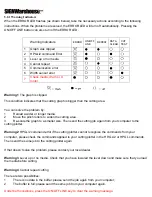
Warning 5

 Communication error  

Check that the serial/USB cable has been connected to the cutting plotter and computer properly.  

If so, then check whether the interface settings are correct. Check that the communication settings in your 

PC are the same as the ones on your cutting plotter (for example – 9600bps, no parity, 8 bits, 1 stop bit). 

Then, press ON/OFF Line key to switch back to On Line mode.  

Warning 6

 Width sensor error  

Check that the pinch rollers are positioned above the grid drum and reload the media again.  

Note: 


In order to identify the warning messages easily, please stick the warning sticker (in accessory box) on the 

side cover of your cutting plotter.  

5.2.2 Error Indicators 


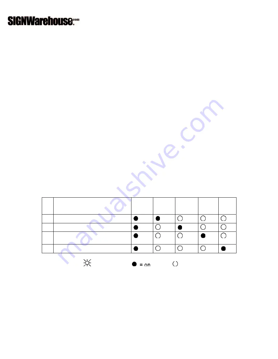
If some mechanical problems occur during the operation, the ERROR LED will turn on. Please follow the 

instructions below to solve the problem. If the cutting plotter still cannot work, please contact your local 

dealer and tell him or her about the error indicator. 


 Error Indicators  

ERROR 

ON/OFF 
LINE  

REPEAT  

DATA 
CLEAR  

CUT 
TEST 

1  

SRAM error  


2  

DRAM error  


3  

Check media, drum, or X 
motor  


4  

Check media or Y motor  


 = flash                

  = off 

Error 1 and 2 

Please contact your local dealer to replace SRAM or DRAM.  

Error 3 

Check the media, drum or X-motor (Drum driven motor). This message indicates that there might be a 

problem on the 

X-axis

. Please check that the drums are working normally and see that the media is well loaded. Then 

turn on the power and reboot the cutting plotter.  

Error 4 

Check the media or Y motor (carriage driven motor). This message indicates that there might be an obstruction 

to the carriage relating to a problem on the 

Y-axis

. Please clear the obstruction and check that the carriage can move 

smoothly. Then turn on the power and reboot the cutting plotter.  


Содержание Enduracut

Страница 1: ......

Страница 2: ...nual at any time without prior notice un authorized modification copying distribution or display is prohibited All comments queries or suggestions concerning this manual please consult with your local...

Страница 3: ...can fly out During an operation do not touch any of the moving parts of this machine such as the carriage Also be careful to make sure that clothing and hair do not get caught Always connect the powe...

Страница 4: ...n 3 1 The Control Panel 3 1 3 2 Cutter Driver Options 3 2 3 3 File Up loader 3 5 3 4 Data Transmission 3 6 4 Basic Maintenance 4 1 Cleaning the cutting Plotter 4 1 4 2 Cleaning the Grid Drum 4 1 4 3 C...

Страница 5: ...ur local dealer for further assistance Item Quantity Cutting Plotter 1 Set Accessories 1 Set 1 Cutting Pad 7 Tweezers 2 AC Power Cord 5 Paper Slitter 3 Desktop Support Brackets 6 RS 232 Cable 1 2 Prod...

Страница 6: ...old the media during cutting C Alignment Ruler To align media with clear guideline marks D Tool Carriage To help perform cutting job with installed blade or pen F Platen The surface for holding and su...

Страница 7: ...3 Figure 1 4 Object Description K AC Power Connector To insert the AC power cord L Fuse 3Amp M Power Switch To turn on or off the machine N USB Connector To connect the machine and a computer through...

Страница 8: ...y direction Keep enough space for the machine accessories and supplies Keep the working area stable avoiding severe vibration Keep the temperature between 10 and 35 50 95 o F in the workshop Keep the...

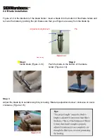
Страница 9: ...e by pushing the pin Make sure that your fingers are away from the blade tip Adjustment depth knob Pin Outward ring Step 1 Step 2 Install blade Figure 2 13 Push the blade to the bottom of the blade ho...

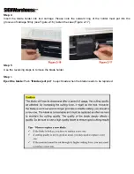
Страница 10: ...utward ring of the holder must put into the grooves of carriage firmly see Figure 2 16 fasten the case Figure 2 17 Step 5 Use the reversing steps to remove the blade holder Step 6 Eject the blade Push...

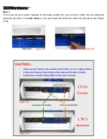
Страница 11: ...es Step 1 Lift the 2 levers at the back side of cutter to raise pinch rollers Figure 2 18 Step 2 Load your media on the platen and slide it under the pinch rollers from either the front side or the ba...

Страница 12: ...e the pinch rollers manually to the proper position Be sure the pinch rollers must be positioned above the grid drum The white marks on the main beam will remind you where the grid drums are Figure 2...

Страница 13: ...se the desktop media support system for roll media Please refer to Chapter 2 2 2 2 3 for hardware setup and Chapter 2 5 1 for media loading 2 4 Cable Connection The cutting plotter communicates with a...

Страница 14: ...firmware at the factory only 2 4 2 RS 232 Interface Connecting to the RS 232 Serial Port 1 For IBM PC PS 2 users or compatibles connect the RS 232C cable to the serial connector of the assigned serial...

Страница 15: ...or stop cutting job light up on line light off off line While in on line mode only ON OFF LINE and PAUSE keys activated While in off line mode the settings in VLCD can be adjusted PAUSE To temporarily...

Страница 16: ...Step 2 Move the carriage to a preferred position Step 3 Press CUT TEST button to perform 3 1 4 Repeat Step 1 Press the ON OFF LINE button to set as off line mode Step 2 Press the REPEAT button to per...

Страница 17: ...Pal can be transmitted directly to the plotter at the DOS prompt and then be cut out Before outputting at the DOS prompt set up a transmission protocol between your cutting plotter and computer by a D...

Страница 18: ...sary clean it with a water rinsed or an alcohol rinsed cloth Wipe the cutting plotter to remove any residues on the cutting plotter Finally absorb water with a soft lint free cloth Wipe all the dust a...

Страница 19: ...cotton swab to wipe away the accumulated dust from the rubber portion of the pinch rollers To prevent the pinch rollers from rotating while cleaning use your fingers to hold the pinch rollers in plac...

Страница 20: ...cutting plotter doesn t plot please check the following items first Is the power cord plugged in properly Is the power cord connected to the power connector properly Is the power switch turned on pro...

Страница 21: ...e pinch rollers to widen the cutting area 3 Re scale the graph to a smaller size Then send the cutting job again from your computer to the cutting plotter Warning 2 HPGL 2 command error if the cutting...

Страница 22: ...lease follow the instructions below to solve the problem If the cutting plotter still cannot work please contact your local dealer and tell him or her about the error indicator Error Indicators ERROR...

Страница 23: ...5 3 Cutting Quality Problems Remove the blade and clean it Please contact customer service personnel for technical support...

Страница 24: ...ax Cutting Speed Diagonal 400 mm sec Software Resolution 0 025 mm Repeatability 0 1mm Re plot Memory 500 Kbytes Interfaces RS 232 Commands HP GL HP GL 2 Configurable Origin Yes Control Panel 6 LEDs 10...

Отзывы: