background image

19

Содержание 513684

Страница 1: ...PSD 109 STRAP DISPENSER ...

Страница 2: ...pect and clean it weekly Replace any worn or broken parts 5 WORK AREA Keep work areas uncluttered and well lighted SAFETY PROCEDURES FOR DISPENSER OPERATION 1 Before loading a coil of strap into the dispenser read the loading and safety instructions Install dispenser properly before using it Maintain proper footing and balance when loading dispenser Do not load dispenser when you are in an awkward...

Страница 3: ...ctions 5 Operation 6 Adjustments 7 Parts Removal Replacement 9 Troubleshooting 13 Parts List 16 INTRODUCTION This dispenser is to be used with power strapping equipment only It is tension actuated and multi roller design can accumulate 30 feet of retracted strap available at an actuation force of 5 pounds SPECIFICATIONS MODEL STRAPPING PSD 109 TYPE WIDTH COIL SIZE Polyester or Polypropylene Up to ...

Страница 4: ...4 RIGHT HAND ORIENTATION LEFT HAND ORIENTATION MAJOR COMPONENTS ...

Страница 5: ... 1 Remove the wing nut then lift the outer flange from the dispenser 2 Swing the lacing latch down from the upper arm Raise the dancer arm and hook it onto the latch This will release the brake and reduce the distance between the dancer arm and the upper arm 3 Before installing the coil of strap note the direction of pay off of the lead end The coil should be placed on the dispenser with the lead ...

Страница 6: ...ke sure the dancer arm is in its lowermost position 2 Cut the strap at the coil and follow steps 1 3 and 5 Method One to load a new coil on the dispenser 3 Tape the lead end of the new coil to the trailing end of the old strap and manually draw the new strap through the roller stacks 4 Remove and discard the old strap and the tape Tape must not be allowed to enter the strapping machine 5 Insert th...

Страница 7: ...ed to the brake block 1 by means of an extension spring 2 connected between the brake block mounting screw 4 and a 5 16 hex head cap screw 3 extending from the dispenser post A just beneath the dispenser shaft mounting hole At this upper location are two 5 16 24 tapped holes Additional spring tension can be gained by removing the 5 16 hex head screw and moving it to the upper hole Make sure the sc...

Страница 8: ...ccumulation depends on the application the factory setting must be considered nominal and some fine tuning may be required The brake is engaged when the cam follower 1 on the brake lever 2 is driven in an upward direction by the cam 3 on the dancer arm shaft 4 The amount of pre travel adjusted into the cam will determine the point at which the brake is engaged To adjust the brake engagement point ...

Страница 9: ...will discharge the brake 2 Disconnect the extension spring 1 at the S hook 2 on the brake lever 3 3 Remove the 1 2 20 stop nut 4 the hex head cap screw 5 the flat washer 6 and the worn brake block 7 from the brake lever 4 Install the brake block and reassemble all parts At this point just snug the stop nut 5 Turn the brake block so that the rolled edge of the inner flange will make as much contact...

Страница 10: ...ke camshaft sprocket during this procedure 5 Apply thread adhesive Loctite 242 or equivalent to the spring stud and reassemble the spring bushing and hex nut 6 Tighten the hex nut until the slack is removed from the chain then tighten no further If the dancer arm compression spring is overtightened the chain or the connecting link may fail during operation 7 Reinstall the pipe cap Failure to insta...

Страница 11: ... attach the dancer arm front bearing 10 assembly to the post 7 Remove the dancer arm assembly with front bearing intact from the post sliding the shaft out of the dancer arm sprocket 11 Note the sprocket key 12 8 Remove the sprocket and the chain assembly 13 from the post 9 Disassemble the sprocket chain stud assembly then replace the chain and reassemble the parts 10 Reassemble the dancer arm ass...

Страница 12: ...If the dancer arm compression spring is overtightened the chain or the connecting link may fail during operation 14 Reinstall the pipe cap 15 Remount the post assembly to the base plate 16 Reinstall the dispenser shaft assembly Position this assembly so that the mounting hub on the rear flange is 2 3 8 from the near face of the post 17 Readjust the strap accumulation Details are in the Adjustment ...

Страница 13: ...ittle or no resistance 9 SYMPTOM Dancer arm motion is erratic 1 SYMPTOM Loose strap between roller stacks CAUSE REMEDY Dispenser accumulation improperly adjusted See Adjustments Section 2 SYMPTOM Strap between dispenser and machine too loose following strapping cycle CAUSE REMEDY Dispenser accumulation improperly adjusted See Adjustments Section 3 SYMPTOM Loose wraps on strap coil CAUSE REMEDY 1 B...

Страница 14: ...ments Section 7 SYMPTOM Dancer arm hits bumper when actuated CAUSE REMEDY Broken dancer arm extension spring Replace dancer arm extension spring See Parts Removal and Replacement Section 8 SYMPTOM Dancer arm swings upward with little or no resistance CAUSE REMEDY Check for broken external dancer arm extension spring chain or connecting link Replace broken parts as needed See Parts Removal and Repl...

Страница 15: ...15 BLANK ...

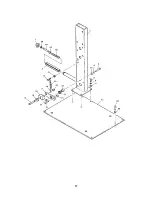
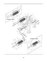
Страница 16: ...16 24 x 1 15 1 426379 Hex nut 5 16 24 16 1 426380 Brake cam follower 3 4 dia 17 1 426381 Retaining Ring external 3 4 18 1 426382 Flat Washer 1 2 19 1 517766 Hex head cap screw 1 2 20 x 3 3 4 20 1 517765 Brake block 21 1 510379 Brake lever 22 1 426386 Elastic stop nut 1 2 20 thin 23 1 510378 Brake lever pivot 24 1 426388 S Hook 25 1 517767 Brake Spring 30 1 426390 Hex nut 3 8 16 62 1 426391 Dancer ...

Страница 17: ...17 ...

Страница 18: ...426404 Hex head cap screw 3 8 16 x 3 4 36 1 517780 Dancer arm bumper 37 1 426406 Bumper spacer 38 2 426407 Upper arm spacer 39 1 426408 Bumper bracket 40 13 426409 Strap accumulation roller 41 2 426410 Spacer 42 1 426411 Dancer arm 43 2 426412 Flanged cartridge bearing 1 dia 44 2 426413 Bearing alignment plate 45 1 426414 Connecting link 35 chain 46 1 426415 Actuation chain 46 1 426416 Hairpin cli...

Страница 19: ...19 ...

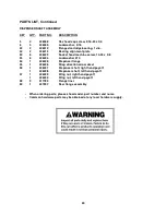
Страница 20: ...e screw 10 24 x 5 8 53 6 426424 Lockwasher 10 54 1 426425 Dispenser flange 55 1 426426 Strap direction arrow decal 56 1 426427 Dispenser shaft right hand payoff 1 426428 Dispenser shaft left hand payoff 57 1 426429 Wing nut right hand payoff 1 426430 Wing nut left hand payoff 58 2 517783 Flange liner 59 1 427597 Rear flange assembly When ordering parts please show model part number and name Common...

Страница 21: ...21 ...

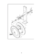
Страница 22: ...lignment plate 46 1 426415 Actuation chain 49 2 426418 Retaining ring external 1 51 1 426420 Sprocket key 52 2 426423 Socket head machine screw 10 24 x 5 8 53 2 426424 Lockwasher 10 58 2 426431 Flat Washer 10 59 1 426432 Brake Cam 60 1 426433 Brake cam shaft 61 1 426434 Camshaft sprocket When ordering parts please show model part number and name Common hardware parts may be obtained at any local h...

Страница 23: ...23 ...

Страница 24: ...SIGNODE 3620 WEST LAKE AVENUE GLENVIEW ILLINOIS 60025 U S A Copyright 2009 Signode 512146 5 2009 ...

Отзывы: