background image

SIGLENT


  108        SDG1000X User Manual


is changed, the phase of the other channel will be changed accordingly. At 

this  point,  aligning  phase  between  the  two  channels  can  be  achieved 

without executing the Eqphase operation. 

3.  Channel  coupling  and  channel  function  are  mutually  exclusive.  When 

channel coupling is enabled, the menu Channel Copy is hidden. 
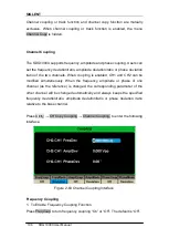
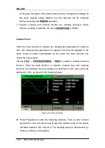
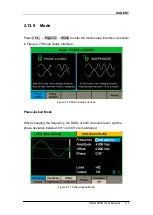
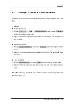


Channel Track 


When the track function is enabled,  by changing the parameters or states of 

CH1,  the  corresponding  parameters  or  states  of  CH2  will  be  adjusted  to  the 

same  values  or  states  automatically.  At  this  point,  the  dual  channels  can 

output the same signal. 
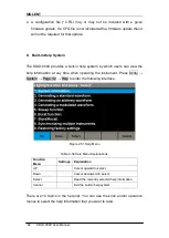
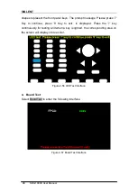
Choose  Utility 

→ CH Copy Coupling → Track to enable or disable the track 

function.  When  the  track  function  is  enabled,  channel  copy  and  coupling 

functions  are  disabled;  the  user  interface  is  switched  to  CH1  and  cannot  be 

switched to CH2, as shown in the following figure. 


Figure 2-64 Track Interface 


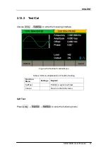
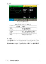
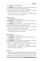
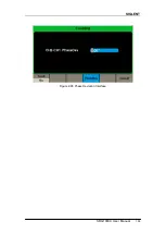
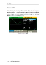
  Press  PhaseDev  to  enter  the  following  interface.  Then  use  the  numeric 

keyboard or knob and arrow keys to input the desired value for the phase 

deviation between CH1 and CH2. The resulting signal is represented by: 

Phase

CH2

-Phase

CH1

=PhaseDev. 

Содержание SDG1000X Series

Страница 1: ...User Manual SDG1000X Series Function Arbitrary Waveform Generator UM0201X E01D 2017 SIGLENT TECHNOLOGIES CO LTD...

Страница 2: ......

Страница 3: ...SIGLENT SDG1000X User Manual I Declaration Copyright SIGLENT TECHNOLOGIES CO LTD All rights reserved Without permission contents in this manual are not allowed to be copied extracted or translated...

Страница 4: ...the instrument is grounded correctly before connecting its input or output terminals Connect the signal wire correctly The potential of the signal wire ground is equal to the earth therefore do not co...

Страница 5: ...ry or hazard that may immediately happen WARNING Indicates an injury or hazard that may not immediately happen CAUTION Indicates that a potential damage to the instrument or other property might occur...

Страница 6: ...th these advantages the SDG1000X can provide users with a variety of high fidelity and low jitter signals and can meet the growing requirements of complex and extensive applications Key Features Dual...

Страница 7: ...SIGLENT SDG1000X User Manual V High precision Frequency Counter 196 kinds of built in arbitrary waveforms Standard interfaces USB Host USB Device USBTMC LAN VXI 11 Optional interface GPIB 4 3 display...

Страница 8: ...6 2 Front Panel Operations 17 2 1 To Set Sine Waveform 18 2 2 To Set Square Waveform 23 2 3 To Set Ramp Waveform 26 2 4 To Set Pulse Waveform 28 2 5 To Set Noise Waveform 32 2 6 To Set DC Waveform 35...

Страница 9: ...ulse Waveform 129 3 5 Example 5 Generate a Noise 131 3 6 Example 6 Generate a DC Waveform 132 3 7 Example 7 Generate a Linear Sweep Waveform 133 3 8 Example 8 Generate a Burst Waveform 135 3 9 Example...

Страница 10: ...SIGLENT VIII SDG1000X User Manual 5 1 Maintenance summary 155 5 2 Contact SIGLENT 156 6 Appendix 157 Appendix A Accessories 157 Appendix B Daily Maintain and Cleaning 158...

Страница 11: ...anual 1 1 Quick Start This chapter covers the following topics Handle Adjustment The Front Rear Panel To Select a Waveform To Set Modulation Sweep Burst To Turn On Off Output To Use Numeric Input To U...

Страница 12: ...al 1 1 Handle Adjustment To adjust the handle position of the SDG1000X please grip the handle by the sides and pull it outward Then make the handle rotate to the desired position Figure 1 1 Viewing Po...

Страница 13: ...ns of the front rear panel Front Panel SDG1000X has a clear and simple front panel which includes a 4 3 inch screen menu softkeys numeric keyboard knob function keys arrow keys and channel control are...

Страница 14: ...des multiple interfaces including Counter 10MHz In Out Aux In Out LAN USB Device Earth Terminal and AC Power Supply Input Figure 1 3 Rear Panel of SDG1000X Aux In Out 10 MHz Clock Input Output Earth T...

Страница 15: ...e function selected Figure 1 4 User Interface 1 Waveform Display Area Displays the currently selected waveform of each channel 2 Channel Status Bar Indicates the selected status and output configurati...

Страница 16: ...he instrument s output impedance of 50 but rather is used to maintain amplitude accuracy into different load values Output Channel output state After pressing corresponding channel output control port...

Страница 17: ...ual 7 1 4 shows the parameters of AM modulation 8 Modulation Parameters Area Shows the parameters of the current modulation function After selecting the corresponding menu use number keys or knob to c...

Страница 18: ...with frequencies from 1 Hz to 60MHz By setting Frequency Period Amplitude High level Offset Low level and Phase a sine waveform with different parameters can be generated Figure 1 6 Sine Display Inte...

Страница 19: ...y Period Amplitude High level Offset Low level Phase and Symmetry a ramp waveform with different parameters can be generated Figure 1 8 Ramp Display Interface 4 Press Waveforms key and then press Puls...

Страница 20: ...ress Noise softkey The generator can generate noise with a 60MHz bandwidth By setting Stdev and Mean noise with different parameters can be generated Figure 1 10 Noise Display Interface 6 Press Wavefo...

Страница 21: ...t press the Arb softkey The generator can generate repeatable arbitrary waveforms with 16K points and frequencies up to 6MHz By setting Frequency Period Amplitude High level Offset Low level and Phase...

Страница 22: ...fying the parameters such as Type Source AM Depth AM Freq Shape etc The SDG1000X can modulate waveforms using AM FM PM ASK FSK PSK PWM and DSB AM etc Pulse waveforms can only be modulated using PWM No...

Страница 23: ...lay Interface 3 Press Burst the Burst function will be enabled Burst signals for sine square ramp pulse or arbitrary waveforms may be generated Start Phase ranges from 0 to 360 and Burst Period ranges...

Страница 24: ...he output of the two channels Choose a channel and press the corresponding Output key the key backlight will be lighted and the output will be enabled Press the Output key again the key backlight will...

Страница 25: ...the digital input selection Figure 1 18 Front Panel Digital Input 1 The numeric keyboard is used to enter the parameter s value 2 The knob is used to increase clockwise or decrease counterclockwise t...

Страница 26: ...et the parameters of basic waveforms directly 2 The Utility key is used to set the auxiliary system function such as output configurations interface setting system setting information performing the i...

Страница 27: ...apter 1 once more This chapter covers the following topics To Set Sine To Set Square To Set Ramp To Set Pulse To Set Noise To Set DC To Set Arbitrary To Set Harmonic Function To Set Modulation Functio...

Страница 28: ...menu select Frequency The frequency parameter area is highlighted in the parameter display window and users can set the frequency value here Figure 2 1 Sine Parameters Display Interface Table2 1 Menu...

Страница 29: ...ument is powered on is the default value or the set value of last power down If Period rather than Frequency is the desired parameter press Frequency Period again to enter the Period mode The current...

Страница 30: ...amplitude The amplitude shown on the screen when the instrument is powered on is the default value or the set value of last power down If setting the waveform s high level is desired press the Amplit...

Страница 31: ...lue or the set value of last power down If you want to set the waveform by low level press the Offset LowLevel key again to switch into the low level parameter the current operation is displayed in in...

Страница 32: ...2 Input the desired phase Use the numeric keyboard to input the parameter value directly and press the corresponding key to select the parameter unit Or use the arrow keys to select the digit to edit...

Страница 33: ...he parameter display window and users can set the duty cycle value here Figure 2 6 Square Parameters Display Interface Table2 2 Menu Explanations of Square Waveform Function Menu Settings Explanation...

Страница 34: ...lt value is 50 1 Press Waveforms Square DutyCycle to set the duty cycle The duty cycle shown on the screen when the instrument is powered on is the default value or the set value of last power down 2...

Страница 35: ...SIGLENT SDG1000X User Manual 25 Figure 2 7 Setting the Duty Cycle Note The methods of setting other parameters of square signal are similar to sine waveform function...

Страница 36: ...lighted in the parameter display window and users can set the symmetry value here Figure 2 8 Ramp Parameters Display Interface Table2 3 Menu Explanations of Ramp Waveform Function Menu Settings Explan...

Страница 37: ...the default value or the set value of last power down 2 Input the desired Symmetry Use the numeric keyboard to input the parameter value directly and press the corresponding key to select the paramet...

Страница 38: ...alue here Figure 2 10 Pulse Parameters Display Interface Table 2 4 Menu Explanations of Pulse Waveform Function Menu Settings Explanation Frequency Period Set the signal frequency or period The curren...

Страница 39: ...le period Pulse duty cycle and pulse width are correlative Once a parameter is changed the other will be automatically changed 1 Press Waveforms Pulse PulWidth to set the pulse width The pulse width s...

Страница 40: ...dge time is limited by the currently specified pulse width limit Users can set rise edge and fall edge independently 1 Press Waveforms Pulse Rise to set the rise edge The rise edge shown on the screen...

Страница 41: ...e digit to edit and then use the knob to change its value The generator will change the waveform immediately Figure 2 12 Setting the Rise Edge Note The methods of setting other parameters of pulse sig...

Страница 42: ...ea is highlighted in the parameter display window and users can set the stdev value here Noise is non periodic signal which has no frequency or period Figure 2 13 Noise Parameters Display Interface Ta...

Страница 43: ...its value Figure 2 14 Setting the Stdev To Set the Mean 1 Press Waveforms Noise Mean to set the mean The mean shown on the screen when the instrument is powered on is the default value or the set val...

Страница 44: ...SIGLENT 34 SDG1000X User Manual Figure 2 15 Setting the Mean...

Страница 45: ...Press Waveforms Page 1 2 DC to enter the following interface Please note that there is a DC offset parameter at the middle of the screen Figure 2 16 DC Setting Interface Note The method of setting of...

Страница 46: ...nd phase Figure 2 17 Arb Parameters Display Interface DDS Table 2 6 Menu Explanations of Arb Waveform Page 1 2 Function menu Settings Explanations Frequency Period Set the signal frequency or period T...

Страница 47: ...lowing interface as shown in Figure 2 18 Figure 2 18 Built in Arbitrary Waveforms Press Common Math Engine Window Trigo or other menus to switch to the desired category the selected category in the me...

Страница 48: ...3 X3 function Airy Airy function Besselj Bessel I function Bessely Bessel II function Dirichlet Dirichlet function Erf Error function Erfc Complementary error function ErfcInv Inverted complementary e...

Страница 49: ...locity curve of explosive oscillation DampedOsc Time displacement curve of damped oscillation SwingOsc Kinetic energy time curve of swing oscillation Discharge Discharge curve of NI MH battery Pahcur...

Страница 50: ...attopWin Flat top weighted window ParzenWin ParzenWin window TaylorWin TaylorWin window TukeyWin TukeyWin tapered cosine window Trigo Tan Tangent Cot Cotangent Sec Secant Csc Cosecant Asin Arc sine Ac...

Страница 51: ...y SquareDuty26 Square waveform with 26 duty SquareDuty28 Square waveform with 28 duty SquareDuty30 Square waveform with 30 duty SquareDuty32 Square waveform with 32 duty SquareDuty34 Square waveform w...

Страница 52: ...e waveform with 88 duty SquareDuty90 Square waveform with 90 duty SquareDuty92 Square waveform with 92 duty SquareDuty94 Square waveform with 94 duty SquareDuty96 Square waveform with 96 duty SquareDu...

Страница 53: ...Sectional sine AM signal FM Sectional sine FM signal PFM Sectional pulse FM signal PM Sectional sine PM signal l PWM Sectional PWM signal Filter Butterworth Butterworth filter Chebyshev1 Chebyshev1 f...

Страница 54: ...SIGLENT 44 SDG1000X User Manual Figure 2 19 Stored Waveform Display Interface Rotate the knob to choose the desired waveform Then select Recall or press the knob to recall the corresponding waveform...

Страница 55: ...l waveform frequency A1 is fundamental waveform amplitude and 1 is fundamental waveform phase The frequencies of the other components called harmonics are all integral multiples of the fundamental wav...

Страница 56: ...onics 2 Press Odd the instrument will output fundamental waveform and odd harmonics 3 Press All the instrument will output fundamental waveform and all the user defined orders of harmonics To Set the...

Страница 57: ...pop up menu The units available are Vpp mVpp and dBc To Select the Harmonic Phase After entering the harmonic setting menu press Harmonic Phase to set the harmonic phase of each order 1 Press Order t...

Страница 58: ...e source internal external modulating frequency frequency deviation modulating waveform and carrier In PM users can set the source internal external phase deviation modulating frequency modulating wav...

Страница 59: ...he parameters of AM modulation are shown in Figure 2 21 Figure 2 21 Setting Interface of AM Modulation Table 2 9 Menu Explanations of the AM Parameters Function Menu Settings Explanation Type AM Ampli...

Страница 60: ...orm selected of the current channel Note Noise can be used as modulating waveform but cannot be used as the carrier 2 External Source When external AM modulation source is selected the generator accep...

Страница 61: ...epth to set the parameter In the 0 modulation the output amplitude is the half of the carrier s amplitude In the 120 modulation the output amplitude is the same with the carrier s amplitude For an ext...

Страница 62: ...f DSB AM Modulation Table 2 10 Menu Explanations of the DSB AM Parameters Function Menu Settings Explanation Type DSB AM DSB Amplitude modulation Source Internal The source is internal External The so...

Страница 63: ...SIGLENT SDG1000X User Manual 53 The methods of setting the parameters of DSB AM are similar to AM...

Страница 64: ...parameters of FM modulation are shown in Figure 2 23 Figure 2 23 Setting Interface of FM Modulation Table 2 11 Menu Explanations of the FM Parameters Function Menu Settings Explanation Type FM Freque...

Страница 65: ...ight the parameter and then use the numeric keyboard or arrow keys and knob to input the desired value The deviation should be equal to or less than the carrier frequency The sum of the deviation and...

Страница 66: ...parameters of PM modulation are shown in Figure 2 24 Figure 2 24 Setting Interface of PM Modulation Table 2 12 Menu Explanations of the PM Parameters Function Menu Settings Explanation Type PM Phase m...

Страница 67: ...hase Dev to highlight the parameter and then use the numeric keyboard or arrow keys and knob to input the desired value Use the numeric keyboard or arrow keys and knob to input the desired value The r...

Страница 68: ...ace of FSK Modulation Table 2 13 Menu Explanations of the FSK Parameters Function Menu Settings Explanation Type FSK Frequency shift keying modulation Source Internal The source is internal External T...

Страница 69: ...hidden To Set Hop Frequency The range of the hop frequency depends on the carrier frequency currently selected Press Hop Freq to highlight the parameter and then use the numeric keyboard or arrow keys...

Страница 70: ...planations of the ASK Parameters Function Menu Settings Explanation Type ASK Amplitude shift keying modulation Source Internal The source is internal External The source is external Use the Aux In Out...

Страница 71: ...in Figure 2 27 Figure 2 27 Setting Interface of PSK Modulation Table 2 15 Menu Explanations of the PSK Parameters Function Menu Settings Explanation Type PSK Phase shift keying modulation Source Inter...

Страница 72: ...62 SDG1000X User Manual Note The methods of setting the parameters of PSK are similar to AM In addition the external modulating signal of PSK must be Square which complies with the CMOS level specifi...

Страница 73: ...own in Figure 2 28 Figure 2 28 Setting Interface of PWM Modulation Table 2 16 Menu Explanations of the PWM Parameters Function Menu Settings Explanation Type PWM Pulse width modulation The carrier is...

Страница 74: ...numeric keyboard or arrow keys and knob to input the desired value as shown in the Figure 2 29 Figure 2 29 Width Deviation Setting Interface The width deviation cannot exceed the current pulse width T...

Страница 75: ...ed the current pulse duty cycle The duty deviation is limited by the minimum duty cycle and current edge time setting Duty deviation and width deviation are correlative Once a parameter is changed the...

Страница 76: ...2 17 Menu Explanations of Sweep Page 1 2 Function Menu Settings Explanation Sweep time Set the time span of the sweep in which the frequency changes from the start frequency to stop frequency Start Fr...

Страница 77: ...key again to switch between the two sweep range modes Start Frequency and Stop Frequency Start Frequency and Stop Frequency are the lower and upper limits of the frequency for sweep Start Frequency S...

Страница 78: ...ency Stop Frequency 2 Frequency Span Stop Frequency Start Frequency Sweep Type SDG1000X provides Linear and Log sweep profiles and the default is Linear Linear Sweep In linear sweep the output frequen...

Страница 79: ...ode Figure 2 34 Log Sweep Interface Sweep Trigger Source The sweep trigger source can be internal external or manual The generator will generate a sweep output when a trigger signal is received and th...

Страница 80: ...eives a CMOS pulse with specified polarity To set the CMOS pulse polarity choose Edge to select Up or Down 3 Manual Trigger Choose Source Manual a sweep will be generated from the corresponding channe...

Страница 81: ...ong burst type trigger source and carrier Burst Type Trigger Source Carrier N Cycle Internal External Manual Sine Square Ramp Pulse Arbitrary Infinite External Manual Sine Square Ramp Pulse Arbitrary...

Страница 82: ...e Cycles Infinite Set the number of the bursts in N Cycle Set the number of the bursts in N Cycle to be infinite Start Phase Set the start phase of the burst Burst Period Set the burst period Source I...

Страница 83: ...Enable trigger out Page 2 2 Return to the previous page Infinite In infinite mode the cycle number of the waveform is set as an infinite value The generator outputs a continuous waveform after receiv...

Страница 84: ...level When the gated signal is true the generator outputs a continuous waveform When the gated signal is false the generator first completes the output of the current period and then stops Waveforms...

Страница 85: ...he default setting is 0 For an Arbitrary Waveform 0 is the first waveform point Burst Period Burst Period is only available when the trigger source is internal It is defined as the time from the start...

Страница 86: ...ger is selected Choose Trig Out as Up or Down the Aux In Out connector at the rear panel will output a trigger signal with specified edge 2 External Trigger Choose Source External the generator accept...

Страница 87: ...ing interface Figure 2 39 Store Recall Interface Page 1 2 Table 2 23 Menu Explanations of Save and Recall Function Menu Settings Explanation File Type State The setting of the generator Data Arbitrary...

Страница 88: ...ary waveform files to C Disk 2 USB Device 0 There is a USB Host interface located on the left side of the front panel which permits users to store recall waveforms or update the firmware version by U...

Страница 89: ...re used the name may be displayed in the store and recall interface abnormally Browse Use the knob to shift between the directories to choose Local C or USB Device 0 Choose Browse press the knob to op...

Страница 90: ...Data File The SDG1000X can recall the data files in csv or dat format from the external memory and transfer them into bin format then store them in the internal memory When it is done the generator wi...

Страница 91: ...c waveform parameters modulation parameters and other utility settings used To save the instrument state the procedures are given as followed 1 Choose the file type to store Press Store Recall File Ty...

Страница 92: ...Down menus Then choose Select to display the character selected in the filename area Delete the character Use the left and right arrow keys to move the cursor in the file name Then choose Delete to de...

Страница 93: ...the file Choose Delete the generator will display prompt message Delete the file Then press Accept the generator will delete the currently selected file To Copy and Paste File SDG1000X supports the in...

Страница 94: ...SIGLENT 84 SDG1000X User Manual 3 Paste the file Rotate the knob to select Local C and press the knob to open its directory Then press Paste...

Страница 95: ...y menu as shown in Figure 2 43 and Figure 2 44 Figure 2 43 Utility Setup Interface Page 1 2 Table 2 26 Menu Explanations of Utility Page1 2 Function Menu Settings Explanation System Set the system con...

Страница 96: ...2 Function Menu Settings Explanation Interface Set the parameters of remote interfaces Sync Set the sync output CLKSource Internal Choose the system clock source External Mode Choose Phase locked or i...

Страница 97: ...System Setup Page 1 2 Function Menu Settings Explanation Number format Set the number format Language English Set the language Chinese PowerOn Default All the settings return to default when power on...

Страница 98: ...able the screen saver 5min 15min 30min 1hour 2hour 5hour Off Disable the screen saver System Info View the system information Firmware Update Update the firmware by the U disk Help View the help infor...

Страница 99: ...Close the Separator Space Use Space as the separator Accept Save the current settings and return to the System menu According to the different choices of the decimal point and the separator the forma...

Страница 100: ...the SDG1000X s setting when the generator is powered on Two choices are available the default setting and the last settings set when the unit was last powered down Once selected the setting will be a...

Страница 101: ...ettings of the system are as followed Table 2 31 Factory Default Setting Output Default Function Sine Wave Frequency 1kHz Amplitude Offset 4Vpp 0Vdc Phase 0 Load High Z Modulation Default Carrier 1kHz...

Страница 102: ...nd the default is On 6 Screen Saver Enable or disable screen saver Press Utility System Page 1 2 ScrnSvr to select On or Off and the default is Off Screen saver will be on if no action is taken within...

Страница 103: ...or 2 Press Utility Page 1 2 Firmware Update Or press Store Recall directly 3 Select the firmware file ADS and choose Recall to update the system software 4 After the updating is finished the generator...

Страница 104: ...the help information at any time when operating the instrument Press Utility System Page 1 2 Help to enter the following interface Figure 2 51 Help Menu Table 2 32 Help Menu Explanations Function Men...

Страница 105: ...the following interface Figure 2 52 Test Cal function Menu Table 2 33 Menu Explanations of Test Cal Setting Function Menu Settings Explain SelfTest Perform a system self test Cancel Return to the Uti...

Страница 106: ...test program LEDTest Run key indicator lights test program BoardTest Run hardware circuit self test program Cancel Return to the Test Cal menu 1 ScrTest Select ScrTest to enter the screen test interfa...

Страница 107: ...e circle between two arrows represents the knob Test all keys and knob and also verify that all the backlight keys illuminate correctly Figure 2 55 Key Test Interface The corresponding area of tested...

Страница 108: ...ey to continue press 8 Key to exit is displayed Press the 7 key continuously for testing and when a key is lighted the corresponding area on the screen will display in blue color Figure 2 56 LED Test...

Страница 109: ...ace Table 2 35 Menu Explanations of Frequency Counter Function Menu Settings Explanation State Off Open the counter On Close the counter Frequency Measured frequency Period Measured period PWidth Meas...

Страница 110: ...to default Accept Save the current settings and return to the previous menu 1 To Select the Parameters to be measured The frequency counter on the SDG1000X can measure parameters including frequency...

Страница 111: ...The default is AC 5 HFR High Frequency Rejection can be used to filter out the high frequency components of a measured signal and improve the measurement accuracy in low frequency signal measurement...

Страница 112: ...ltage will not be the same as the output voltage setting on the generator This function is used to match the displayed voltage with the expected one This setting does not actually change the output im...

Страница 113: ...t inverted when the waveform is inverted EqPhase Press Utility Output Setup EqPhase to align the phases of CH1 and CH2 Choosing the menu will re configure two channels and enable the generator to outp...

Страница 114: ...Explanation CH1 Switch CH1 Output the waveform of CH1 CH1 CH2 Output the waveform of CH1 CH2 CH2 Switch CH2 Output the waveform of CH2 CH1 CH2 Output the waveform of CH1 CH2 Return Save the current o...

Страница 115: ...one channel to the other one Press Utility CH Copy Coupling Channel Copy to enter the following interface Figure 2 62 Channel Copy Interface Table 2 38 Menu Explanations of Channel Copy Function Menu...

Страница 116: ...ng is enabled CH1 and CH2 can be modified simultaneously When the frequency amplitude or phase of one channel as the reference is changed the corresponding parameter of the other channel will be chang...

Страница 117: ...itude deviation between CH1 and CH2 The resulting signal is represented by AmplCH2 AmplCH1 AmplDev Ratio the amplitude ratio of CH1 and CH2 The resulting signal is represented by AmplCH2 AmplCH1 AmplR...

Страница 118: ...r states of CH2 will be adjusted to the same values or states automatically At this point the dual channels can output the same signal Choose Utility CH Copy Coupling Track to enable or disable the tr...

Страница 119: ...SIGLENT SDG1000X User Manual 109 Figure 2 65 Phase Deviation Interface...

Страница 120: ...rameters or GPIB address Figure 2 66 Interface Settings Table 2 39 Menu Explanations of Interface Function Menu Settings Explanation GPIB Set the GPIB address LAN State On Turn on LAN Off Turn off LAN...

Страница 121: ...uggested to do as the following steps 1 Connect the device Connect the USB Device interface at the rear panel of SDG1000X with the PC via a USB cable 2 Install the USB driver NI Visa is recommended 3...

Страница 122: ...terminal of the PC 2 Install the driver of GPIB card Please install the driver for the GPIB card which has been connected to your PC 3 Set the GPIB address Choose Utility Page 1 2 Interface GPIB to e...

Страница 123: ...he device Connect the generator to your PC or the LAN of your PC using a network cable 2 Configure network parameters Choose Utility Page 1 2 Interface LAN State to turn on LAN Then choose LAN Setup t...

Страница 124: ...d on at the next time 3 To Set Gateway The format of gateway is nnn nnn nnn nnn and each nnn ranges from 0 to 255 It is recommended to acquire an available gateway from your network administrator Pres...

Страница 125: ...DHCP to select On or Off to turn DHCP mode on or off The default is Off 3 Communicate with PC remotely Open Measurement Automation Explorer of NI After adding the LAN device VISA TCP IP Resource succe...

Страница 126: ...ut Interface Table 2 40 Menu Explanations of Sync Output Function Menu Settings Explanation State Off Close the sync output On Open the sync output Channel CH1 Set the sync signal of CH1 CH2 Set the s...

Страница 127: ...ulse with about 50ns pulse width For AM FM PM and PWM the frequency of the sync signal is the modulating frequency For ASK FSK and PSK the frequency of the sync signal is the key frequency 2 When exte...

Страница 128: ...ear panel If not the prompt message No external clock source would be displayed and the clock source would be switched to Internal Sync methods for two or more instruments Synchronization between two...

Страница 129: ...enter the mode setup Interface as shown in Figure 2 70 Mode Setup Interface Figure 2 70 Mode Setup Interface Phase locked Mode When changing the frequency the DDSs of both channels reset and the phas...

Страница 130: ...the frequency neither channels DDS resets and the phase deviation between CH1 and CH2 changes at random When the independent mode is enabled the phase parameter cannot be modified and the menu Phase...

Страница 131: ...H2 will take effect once any of the following conditions is met When overvoltage protection occurs a message will be displayed and the output is disabled The absolute value of input voltage is higher...

Страница 132: ...ate a Ramp Waveform Example 4 Generate a Pulse Waveform Example 5 Generate a Noise Example 6 Generate a DC Waveform Example 7 Generate a Linear Sweep Waveform Example 8 Generate a Burst Waveform Examp...

Страница 133: ...and choose the unit MHz The frequency is set to 1MHz Set the Amplitude 1 Press Amplitude HighLevel to choose Amplitude which will display in blue color 2 Input 5 from the keyboard and choose the unit...

Страница 134: ...SIGLENT 124 SDG1000X User Manual Figure 3 1 Generate a Sine Waveform...

Страница 135: ...ess Amplitude HighLevel to choose Amplitude which will display in blue color 2 Input 2 from the keyboard and choose the unit Vpp The amplitude is set to 2Vpp Set the Offset 1 Press Offset LowLevel to...

Страница 136: ...SIGLENT 126 SDG1000X User Manual Figure 3 2 Generate a Square Waveform...

Страница 137: ...Amplitude which will display in blue color 2 Input 100 from the keyboard and choose the unit mVpp The amplitude is set to 100mVpp Set the Offset 1 Press Offset LowLevel to choose Offset which will di...

Страница 138: ...SIGLENT 128 SDG1000X User Manual When the period amplitude offset phase and symmetry are set the waveform generated is shown in Figure 3 3 Figure 3 3 Generate a Ramp Waveform...

Страница 139: ...1 Press Amplitude HighLevel and choose the HighLevel which will display in blue color 2 Input 5 from the keyboard and choose the unit V The high level is set to 5V Set the LowLevel 1 Press Offset Low...

Страница 140: ...l 2 Input 20 from the keyboard and choose the unit ns The delay is set to 20ns When the frequency high level low level pulse width and delay are set the waveform generated is shown in Figure 3 4 Figur...

Страница 141: ...e Stdev which will display in blue color 2 Input 0 5 from the keyboard and choose the unit V The stdev is set to 0 5 V Set the Mean 1 Press Mean to choose Mean which will display in blue color 2 Input...

Страница 142: ...aveform 1 Press Waveforms Page 1 2 DC to choose the DC waveform Set the Offset 1 Press Offset and choose Offset which will display in blue color 2 Input 3 from the keyboard and choose the unit Vdc The...

Страница 143: ...oose Amplitude which will display in blue color Input 5 from the keyboard and choose the unit Vpp to set the amplitude to 5Vpp 2 Press Offset LowLevel to choose Offset which will display in blue color...

Страница 144: ...SDG1000X User Manual Set the sweep profiles Press Type and choose Linear When all parameters above are set the linear sweep waveform generated is shown in Figure 3 7 Figure 3 7 Generate a Linear Swee...

Страница 145: ...ncy to 10kHz 2 Press Amplitude HighLevel to choose Amplitude which will display in blue color Input 4 from the keyboard and choose the unit Vpp to set the amplitude to 4Vpp 3 Press Offset LowLevel to...

Страница 146: ...e the unit Cycle to set the burst cycle count to 5 Set the delay Press Page 1 2 to choose Delay and input 100 from the keyboard and choose the unit s to set the delay to 100 s When all parameters abov...

Страница 147: ...choose Amplitude which will display in blue color Input 1 from the keyboard and choose the unit Vpp to set the amplitude to 1Vpp 4 Press Offset LowLevel and choose Offset which will display in blue co...

Страница 148: ...SIGLENT 138 SDG1000X User Manual Figure 3 9 Generate an AM Modulation Waveform...

Страница 149: ...and choose Amplitude which will display in blue color Input 1 from the keyboard and choose the unit Vpp to set the amplitude to 1Vpp 4 Press Offset LowLevel and choose Offset which will display in blu...

Страница 150: ...SIGLENT 140 SDG1000X User Manual Figure 3 10 Generate a FM Modulation Waveform...

Страница 151: ...choose Amplitude which will display in blue color Input 5 from the keyboard and choose the unit Vpp to set the amplitude to 5Vpp 4 Press Offset LowLevel and choose Offset which will display in blue co...

Страница 152: ...SIGLENT 142 SDG1000X User Manual Figure 3 11 Generate a PM Modulation Waveform...

Страница 153: ...ghLevel and choose Amplitude which will display in blue color Input 5 from the keyboard and choose the unit Vpp to set the amplitude to 5Vpp 4 Press Offset LowLevel and choose Offset which will displa...

Страница 154: ...SIGLENT 144 SDG1000X User Manual Figure 3 12 Generate a FSK Modulation Waveform...

Страница 155: ...he frequency to 5kHz 3 Press Amplitude HighLevel and choose Amplitude which will display in blue color Input 5 from the keyboard and choose the unit Vpp to set the amplitude to 5Vpp 4 Press Offset Low...

Страница 156: ...SIGLENT 146 SDG1000X User Manual Figure 3 13 Figure 3 13 Generate an ASK Modulation Waveform...

Страница 157: ...ress Amplitude HighLevel and choose Amplitude which will display in blue color Input 5 from the keyboard and choose the unit Vpp to set the amplitude to 5Vpp 4 Press Offset LowLevel and choose Offset...

Страница 158: ...SIGLENT 148 SDG1000X User Manual Figure 3 14 Generate a PSK Modulation Waveform...

Страница 159: ...board and choose the unit Vpp to set the amplitude to 5Vpp 4 Press Offset LowLevel and choose Offset which will display in blue color Input 0 from the keyboard and choose the unit Vdc to set the offse...

Страница 160: ...SIGLENT 150 SDG1000X User Manual Figure 3 15 Generate a PWM Modulation Waveform...

Страница 161: ...frequency to 2kHz 3 Press Amplitude HighLevel and choose Amplitude which will display in blue color Input 4 from the keyboard and choose the unit Vpp to set the amplitude to 4Vpp 4 Press Offset LowLev...

Страница 162: ...SIGLENT 152 SDG1000X User Manual Figure 3 16 Generate a DSB AM Modulation Waveform...

Страница 163: ...hanically and electrically 2 Inspect the entire instrument In case there is any mechanical damage or defect or the instrument does not operate properly or fails in the performance tests notify the SIG...

Страница 164: ...n 3 After the inspections above restart the generator 4 If the generator still doesn t work after checking please contact SIGLENT 2 If there is no waveform output after setting the parameters please d...

Страница 165: ...SIGLENT will provide repair or replace the unit as described in the complete warranty statement To arrange for service or obtain a copy of the complete warranty statement please contact your nearest...

Страница 166: ...al 5 2 Contact SIGLENT SIGLENT TECHNOLOGIES CO LTD Address 3 F NO 4 building Antongda Industrial Zone 3rd Liuxian Road 68th District Baoan District Shenzhen P R China Tel 400 878 0807 E mail sales sig...

Страница 167: ...ries Function Arbitrary Waveform Generator Accessories Standard Accessories Quick Start Guide A Calibration Report A Power Line that fits the standard of the destination country A USB Cable Optional A...

Страница 168: ...t from all power sources and clean it with a mild detergent and water Make sure the instrument is completely dry before reconnecting it to a power source To clean the exterior surface perform the foll...

Отзывы: