


Hinging Flight Surfaces:
The proper hinging of the flight surfaces for any model is very
important.
This is even more so with giant-scale models.
Improperly installed hinges can and will have a detrimental effect
on how the model flies in terms of precise control response.
Further, it is imperative that each hinge be securely glued in place.
The Edge 540T ARF kit includes excellent Super Hinge Point
hinges. These are high quality, very strong, and easy to install.
Also note that all of the required hinge mounting holes have been
pre-drilled for your convenience. The correct mounting of these
hinges requires the use of 30-minute epoxy - never use 5 or
15-minute epoxy types for gluing these hinges in place. It's most
efficient to mix 1/2-ounce batches of glue at a time for hinge
installation. If during the hinging process the glue begins to feel
"thick", mix a fresh batch and continue on.
Note that this section is generic to hinging all of the flight surfaces.
The same techniques and materials should be used. All five of the
flight surfaces - 2 ailerons, 2 elevators, and the rudder - can be
hinged at this time. To illustrate this instruction, we are using the
left stabilizer and elevator half. We always suggest installing the
hinges into the flight surface (elevator, in this case) first, followed
by then mounting the flight surface to its corresponding part.
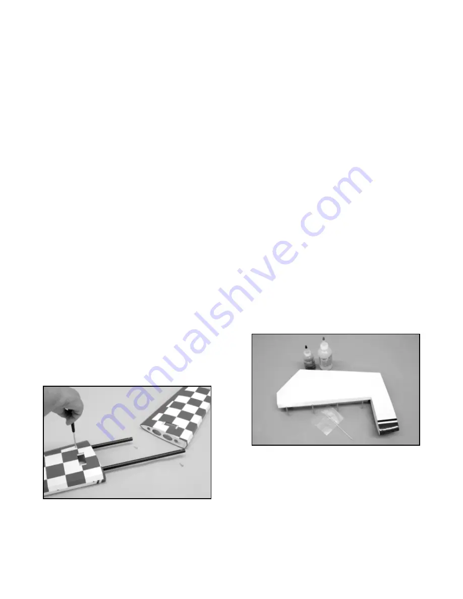
1) We suggest wiping down each hinge with alcohol before it is
installed. This removes all oils, etc. from the hinge, allowing the
best bonding surface for the epoxy.
2) Mix a fresh batch of 30-minute epoxy in a cup. Use a thin stick
(we like using bamboo skewers for this purpose) to apply glue into
one of the hinge holes in the elevator. Also apply glue to the ribbed
surface of one half of one of the hinges. Insert the hinge into the
hole in the elevator until it is fully in place. The center hinge pin
should be aligned in parallel with the hinge line of the elevator.
Quickly wipe off any oozing glue with a paper towel and alcohol.
Orient the hinge at 90
O
to the hinge line, allowing full movement up
and down. Repeat this process, installing the remaining hinges.
3) With the hinges in place and properly oriented, allow the epoxy
to cure for at least 4 hours to ensure the best bond. After the glue
has cured, work each hinge repeatedly through the full range of
movement. This will break up any glue that may have gotten into
the hinge area.
Continue doing this until each hinges moves
absolutely freely with no binding at all.
4) Mix a fresh batch of 30-minute epoxy.
Use a thin stick or
bamboo skewer to apply glue into each hinge hole in the
stabilizer. Apply glue to the exposed ribbed ends of each hinge
half. Carefully installed each hinge half into their corresponding
holes in the stabilizer. Press the elevator half uniformly into place
against the stabilizer hinge line. You want to leave the minimum
possible gap. Use alcohol and paper towels to carefully remove
any visible signs of glue at each hinge location.
7
Insert the front and rear mounting tubes in place into the stab,
making sure they both bottom out against their stops. Insert the
pointed end of the music wire into one of the pre-drilled holes on
the bottom of the stab. Press the music wire against the aluminum
tube and rotate the tube inside the stab. This will scribe a mark on
the tube.
Repeat this process with the remaining stab tube.
Remove the tubes from the stab half.
4) Use an electric drill and a .081 dia. drill bit (#46 index size), to
drill a hole through the aluminum tube and into the hardwood
insert at the scribed location on the tube, at 90
O
to the length of the
tube. Do not drill all the way through the tube. In the interest of
accuracy, we used a drill press for this step. Repeat this process
with the other tube end. Clean up any debris on the tubes where
the holes were drilled, using sandpaper to smooth it.
Using one of the T2.6 x 16mm PWA screws and a Phillips Head
screwdriver, tap the hole just drilled in the tube, running the screw
about 3/4 of the way into the tube. To do this correctly, make just
a 1/2 turn or so with the screw, back it out a bit and then screw it
in another 1/2 turn or so. Repeat this tapping process - a little in,
a little out - until the hole is tapped. Now do the same thing with
the remaining tube. Remove any debris on the surface of the
mounting tubes with sandpaper. Install the two now drilled and
tapped tubes back into the stab half.
Install the two retaining
screws into the stab and tube ends, bringing the heads of both
screws down to the surface of the stab - there is no need to over-
tighten these screws.
5) With the front and rear mounting tubes and the retaining screws
now accurately in place in one of the stab halves, the same thing
has to be done with remaining stab half. Slide the opposite stab
half onto the mounting tubes, all the way to the internal stops.
Chuck the .081 dia. drill bit into an electric hand-held drill. Using
the two hole locations on the bottom surface of the stab, insert the
bit into each hole and use a little pressure to mark the hole
locations onto the ends of both tubes. Remove the stab half from
the tubes and remove the retaining screws from the opposite stab
half and then remove both tubes. Drill the now marked tube ends
at 90
O
with the .081 dia. drill bit, again about 3/4 of the way through
the tubes. Tap the two holes with a T2.6 x 16mm screw, using the
technique described earlier. Remove any debris from the surface
of the two tubes with sandpaper.
Insert the mounting tubes into one of the stab halves and install
the retaining screws. Install the exposed tube ends through the
fuselage holes. Slide the remaining stab half in place onto the
tubes, all the way up to the fuselage side. Install the two retaining
screws. This completes the stab mounting and retaining screw
installation. Remove the stab halves and tubes from the fuselage.