All rights reserved - © 2016
RED1
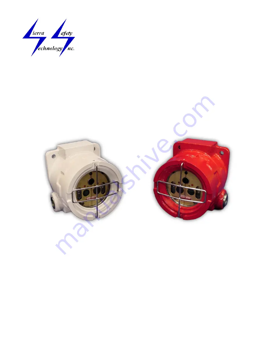
Models HST, HE1, HE2, HE3, HE4, and HNT
Technical Support and Installation Manual
Страница 1: ...All rights reserved 2016 RED1 Models HST HE1 HE2 HE3 HE4 and HNT Technical Support and Installation Manual ...
Страница 2: ...ded View 10 Figure 2 RED1 Housing Dimensions 10 Figure 3 RED1 Detector Module Front 11 Figure 4 RED1 HE1 to HE4 Detector Module Back 11 Figure 6 RED1 Field of View 12 Figure 7 Configuration Switches 13 Figure 8 RED1 HE1 to HE4 Wiring 13 Figure 9 Typical Panel Wiring 14 7 TABLES 15 7 1 Dip Switch Settings 15 7 2 Connectors 16 7 3 Verify Aux Relay Configurations 16 7 4 Fault Table 17 7 5 False Alarm...
Страница 3: ...nty to the declaration of a verified fire The Aux Relay activates when the detector determines that the Lens or UV system is not working properly The RED1 detector is mounted in an approved NEMA 4X weather tight housing The housing is explosion proof rated for Class I Divisions 1 2 Groups B C D Class II Divisions 1 2 Groups E F G and Class III locations All of the electronics are mounted inside of...
Страница 4: ...tected by the sensor elements of the detector Even objects such as scaffolds and ladders within the field of view will impact the detector s response Ultraviolet and Infrared sensors cannot see through most types of glass or plastic even if the glass or plastic is visually transparent For coverage of a large area the detectors should be located with overlapping fields of view see Figure 6 Flame de...
Страница 5: ...vity The factory default is 80 feet SW1 and SW2 are off Note Different fuels emit energy at differing rates For example a fire involving fuel oil does not emit energy at the same rate as gasoline 2 5 2 Verify Control Models RED1 HE1 to HE4 have a Verify Relay The Verify function is armed when the detector detects a fire and will trigger when the Verify function has confirmed the fire The switches ...
Страница 6: ...flashes then the switch is in the off position If two LEDs flash then the switch is in the on position Note that switch 7 overrides switch 8 and switch 6 overrides switch 7 see Latching 2 6 2 Normal Mode In Normal Mode the LEDs will flash briefly every 8 seconds Whenever the device is in any other mode the flash every 8 seconds is suspended until the detector returns to Normal Mode 2 6 3 Fire Mode...
Страница 7: ...7 1 Fire Relay The Fire Relay will energize when the detector declares a fire Using switches the relay may be configured for Latching or Non Latching operation The Fire Relay connector J2 provides 2 connections for each of the common normally open and normally closed contacts of the Fire Relay If the Fire Relay is configured for Latching then it will remain energized until power is removed If the ...
Страница 8: ...V sensor The Pins on the J3 connector see section on Connectors labeled Aux In and Aux Out provide connections for a Normally Open contact on the HE2 and HE3 models or a Normally Closed contact on the HE1 and HE4 models 3 Installation 3 1 Housing and Conduit 3 1 1 Mounting the Housing The housing is mounted by using the two 3 diameter holes located in ears on the back of the housing The two condui...
Страница 9: ... points are internally connected either or both may be used The Fire Relay connector labeled FIRE has connection points for Normally Open Normally Closed and Common The Normally Open connections are labeled Open the Common contacts are labeled Center and the Normally Closed contacts are labeled Closed 3 2 3 Verify Relay The Verify Relay connector J3 has two connections points for each connection t...
Страница 10: ...fire protection systems should be inspected in accordance with NFPA 72 or the appropriate local codes The self test functions incorporated in the detectors reduce the need for most regular maintenance procedures If a detector indicates a fault use the troubleshooting section of this document 4 1 Lens Cleaning The most common fault is a UV Test Fault Regular cleaning of the Lens will diminish this ...
Страница 11: ...tions Screw terminals 14 22 AGW wire size Weight Approximately 3 pounds Housing Dimensions 5 4 x 4 8 x 3 7 Material Copper free Aluminum with Red or White epoxy finish Conduit Two 3 4 inch NPT Rating NEMA 4X Explosion proof Class I Divisions 1 2 Groups B C D Class II Divisions 1 2 Groups E F G Class III Spectral Response UV 185 to 260 nanometers IR 0 715 to 3 5 microns Visible 480 560 nanometers S...
Страница 12: ...erra Safety Technology Inc www sierrasafety com All rights reserved 2016 Page 10 of 20 6 Figures Figure 1 RED1 Exploded View Figure 2 RED1 Housing Dimensions Housing Base Detector Module Housing Top Grill ...
Страница 13: ...e 3 RED1 Detector Module Front Figure 4 RED1 HE1 to HE4 Detector Module Back LED 2 CONFIGURATION SWITCHES SW1 SW9 MOUNTING SCREW 2 Locations LED 1 FIRE RELAY CONNECTOR J2 VERIFY AND AUX RELAY CONNECTOR J3 FAULT RELAY CONNECTOR J4 POWER CONNECTOR J5 Pin 1 on all connectors is located on this side ...
Страница 14: ... Technology Inc www sierrasafety com All rights reserved 2016 Page 12 of 20 Figure 6 RED1 Field of View 20 ft 20 ft 40 ft 40 ft 60 ft 60 ft 80 ft 0 30 15 15 30 80 ft 45 45 60 75 60 75 Level 1 Level 3 Level 2 Level 4 ...
Страница 15: ...ology Inc www sierrasafety com All rights reserved 2016 Page 13 of 20 Figure 7 Configuration Switches Figure 8 RED1 HE1 to HE4 Wiring SW1 SW2 SW3 SW4 SW5 SW6 SW7 SW8 SW9 SW1 Shown in off position SW2 Shown in on position ...
Страница 16: ...Sierra Safety Technology Inc www sierrasafety com All rights reserved 2016 Page 14 of 20 Figure 9 Typical Panel Wiring RED1 Detectors ...
Страница 17: ...vel 6 Max Verify longer OFF ON ON Level 7 Verify Disabled ON ON ON 7 1 3 Fire Relay Latching Control Fire Relay Description SW6 Latching Alarm Until Power Down Reset OFF Non Latching Alarm Until No Fire 5 to 10 sec ON 7 1 4 Verify Relay Latching Control HE1 to HE4 Models only Verify Relay Description SW7 Latching Alarm Until Power Down Reset OFF Non Latching Alarm Until No Fire 5 to 10 sec ON SW6 ...
Страница 18: ...mmon Side of Relay Pin 3 Pin 4 Verify Relay NO or NC Side of Relay Pin 5 Aux Relay Common Side of Relay Pin 6 Right Most Aux Relay NO or NC Side of Relay 7 2 3 Fault Connector J4 Fault Relay Description Normally Energized State Pin 1 Left Most Normally Closed Side of Relay Pin 2 Middle Common Side of Relay Pin 3 Right Most Normally Open Side of Relay 7 2 4 RED1 Power Communications Connector J5 Po...
Страница 19: ...false alarm stimuli False Alarm Source Distance Unmodulated Modulated Resistive Electric Heater 1320 Watt 6 Feet No Response No Response Fluorescent Lights 2 40 Watt Bulbs 6 Feet No Response No Response Incandescent Light 100 Watt 6 Feet No Response No Response Direct Sunlight 93 Million Miles No Response No Response 7 6 Detector Response to Fuels Table Detector Response To Various Fuels Fuel Dist...
Страница 20: ...the detector for servicing 8 2 1 Fault Type 1 UV Test Fault Clean the lens and grill per section 4 1 Reset the detector remove and replace power If the fault persists it may indicate a bad UV tube or UV source tube factory service is required 8 2 2 Fault Type 2 Configuration Fault The program s sum check is invalid Factory service is required 8 2 3 Fault Type 3 Calibration Fault The Calibration co...
Страница 21: ...detector should come on Two the fire relay should energize Check the dipswitch settings SW1 SW2 and SW8 should be off SW3 SW7 have no impact Connect an ohmmeter across the Fire relay connections at the Fire connector Pin 1 and Pin 3 of J2 Run a fire test per section 3 3 1 If the relay closes 0 ohms on the meter and the LEDs come on the detector is operating normally Check external alarm initiating...
Страница 22: ...y 1 5 7 Field of View 2 9 Fire Relay 1 4 5 7 16 Fire Following 2 Fire Mode 4 H Housing 1 6 9 I Input voltage 9 L Latching 2 3 15 LEDs 2 4 19 Lens Cleaning 8 M Mode Alarm 2 Fire Following 2 Latching 2 Normal 2 N NEMA 1 9 Normal Mode 2 4 P Power 4 7 16 R Range 2 RED1 1 2 3 9 Color 9 Relay Contacts 9 Control 3 S Seal Off 6 Sensitivity 3 Range 2 Switches Configuration 3 15 Sensitivity 3 T Temperature ...