


Wireless Room Sensor Solution
WRS Display
The WRS display may show three different views, depending on the display mode:
•
Current Temperature and Occupancy Mode
(see Figure 3). Shown on both WRS models with
a display, the LCD panel can be con
fi
gured to always show the information or temporarily show
the information only after a button is pushed.
WLAN0079R1
OCCUPIED MODE
UNOCCUPIED MODE
Figure 3. Current Temperature and Occupancy Mode View.
When an HMI cable is inserted into the WRS, the current temperature and occupancy mode view is
shown along with the
and
icons (see below for details on these icons).
•
Setpoint
(see Figure 4). This view is available on full-featured WRS models only and is shown after
the
+
or
−
button is pushed.
WLAN0079R1
OCCUPIED MODE
UNOCCUPIED MODE
SETPOINT INDICATOR
(71 F)
Figure 4. Setpoint View.
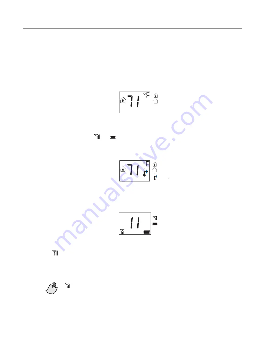
•
Diagnostics
(see Figure 5). This information is shown after an RTS passkey (P/N 544–643) is
inserted in the WRS RJ-11 port of either of the two WRS models with a display.
TEC ADDRESS
WLAN0080R1
RF STRENGTH
BATTERY VOLTAGE
TEC ADDRESS
(11)
Figure 5. Diagnostics (Passkey) View.
represents the percentage of WRS communications that were successfully completed:
4 bars = 100% to 99.5
3 bars = 99.5% to 99%
2 bars = 99% to 98%
1 bar = 98% to 96%
0 bar = 96% to 0%
does not display real-time wireless communication status. It is updated every 60 seconds.
Revision Date: July 10, 2008
11
Siemens Building Technologies, Inc.


