INTEGRAL RSA
K21-04.10
4/8
Application controllers
en - 06.2001
Siemens Building Technologies
Landis & Staefa Division
Mounting and dimensions [mm]
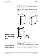
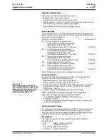
The base unit can be fixed with four screws directly onto any surface, or
snap-mounted on two rails.
If mounting rails are used, proceed as follows:
1. Fix the top rail
2. Fit the bottom rail to the base unit and snap-mount the unit onto the
top rail
3. Fix the bottom rail
The terminal connections are grouped in blocks, making for easy wiring
without the need to remove the unit cover.
243
92.00156
125
149
Caution:
The application module is a static-
sensitive component.
Before inserting or removing the mo-
dule, the base unit must be discon-
nected from the power supply.
Do not touch the contact pins in the
base unit.
252
52
162
59
49
24
15
203
92.00158
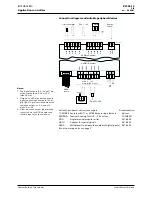
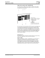
Opening the controller
1. Ensure that the necessary EMC precautions have been taken.
2. Undo the four cross-head screws between the terminal blocks.
3. Carefully lift off the cover.
For the NRK16-B/A: Press the four white plastic clips together with pliers,
carefully release the pcb for the display and operating unit, and pull
upwards.
Observe similar precautions when re-assembling the controller, paying
special attention to the fibre optic cables of the LEDs and the extension of
switch S100.
Caution:
Do not touch the PCB. Electronic
components can be damaged by
electrostatic discharge. Handling the
PCB without observing electrostatic
precautions will invalidate the
warranty.


