INTEGRAL RSA
K21-04.10
5/8
Application controllers
en - 06.2001
Siemens Building Technologies
Landis & Staefa Division
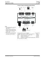
Connection diagram and suitable peripheral devices
Notes:
1. The digital outputs (C, D, E and F) are
active-type outputs, DC 0 or 24 V
(max. 50 mA).
2. Outputs C and D may be used as both
digital
and
analogue outputs. The di-
gital (24 V) signal switchs on when the
analogue output is > 5 V, and off
when it is < 3 V.
3. Other input and output types may be
connected via the NTIO adapter and
suitable input or output modules.
Suitable peripheral devices (examples)
Documentation
T1/Ni1000 Sensors with T1 or Ni1000 measuring elements
Various
ZM100/A
Teminal housing for DC 0 ... 10 V valves
CA2N4591
NTIO
Single terminal module carrier
K21-06.50
NATU
Adapter for special signals
K21-06.52
NMID
Multiplexer (to increase the number of digital inputs) K21-06.55
Room operating units, see page 7
-
1
+
2
A
UI01
-
1
+
2
B
UI02
-
1
+
2
C
UI03
-
1
+
2
D
UI04
-
1
+
2
E
UI05
-
1
+
2
F
UI06
-
1
+
2
G
UI07
-
1
+
2
H
UI08
-
1
+
2
I
UI09
-
1
+
2
J
UI10
-
1
+
2
K
UI11
+
4
+
6
UO07
3
-
4
+
UO01
UO02
UO03
UO04
A
B
E
UO05
F
UO06
3
-
4
+
3
-
5
+
3
-
5
+
3
-
4
+
5
+
3
-
4
+
5
+
AC
24 V
DC
15 V
TE
L
(+)
N
(-)
GND
+15
92.00160en
3 = COMMON
4 = DC 0 ... 10 V
5 = digital (DC 0 / 24 V)
-
+
+15
GND
NMID
C
D
3
ZM100
4
Service
3 4
3
5
Relay, 24 VDC
NBRN
(RS485)
1 2
1 2
1 2
1 2
GND
+15
DC 0 ... 10 V
digital
T1
Remote
control
SAPIM I/O number
SAPIM I/O number
1 2
AC 24 V
L
S
N
S
T1/Ni1000


