INTEGRAL RSA
K21-04.10
8/8
Application controllers
en - 06.2001
Siemens Building Technologies
Landis & Staefa Division
92.00159
1
2
3
5
4
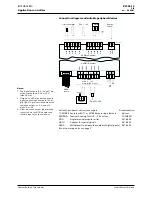
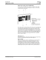
Simple local operation with the NRK16-B/A
The cover plate of the NRK16-B/A incorporates facilities for direct opera-
tion. The functions of the selectable display and switches are defined by
the application module selected.
1 Rocker switches
2 Four-digit 7-segment LED display
3 Display-selector keys, from top:
Measured value 1
Measured value 2
Setpoint 1
Setpoint 2
4 Channel LEDs
corresponding to selector keys
5
<+>
and
<>
for setpoint entry
Each rocker switch has three positions with functions which vary depending
on the application module used. The allocation of the two setpoints and
two measured values also depends on the application. These four values
can be displayed in the four-digit LED display panel by use of the appropri-
ate selector key. The setpoints can be modified with the
<+>
and
<>
keys;
these also operate as repeating keys when continuously depressed. Each of
the four values is associated with one of the red channel LEDs. With some
applications, the setpoints can have upper and lower limits, adjustable
from an operator terminal.
LED function test
Depressing the two lower selector keys simultaneously should cause all seg-
ments of the display panel and the channel LEDs to light up..
Alarm handling
Subject to the application selected, the display panel can also be used to in-
dicate alarms. A code between A1 and A9 can be displayed (A1 A8 for
alarms defined in accordance with the application, and A9 for a common
alarm). The operation of the controller is not affected by the presence of an
alarm. While the measured value or setpoint is displayed, the associated
channel LED will flash, i.e. the alarm remains active. The alarm code can be
displayed again by pressing the two upper selector keys simultaneously.


