12
Siemens
A6V12681516_enUS_a
Smart Infrastructure
10/12/2022
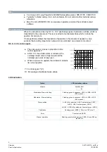
Diagrams
Connection terminals
G0
System neutral
Y
Control signal DC 0...10 V
G
System potential (AC/DC 24 V)
Connection diagrams
N
= Controller
Y
= Actuator
SP, G = System potential AC 24 V
SN, G0 = System neutral
Y = Control signal
Dimensions
mm (inch)
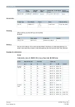
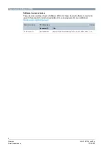
Revision numbers
Type
Valid from rev. no.
SSB161.05U
..A
G Y G0
(Y)
SN (-)
AC
24
V
(D
C
24 V)
2AF
76.7
(3")
27.7
(1.1")
92
.6
(3
.7)
"
A
6
V
1
2
6
8
1
5
1
1
Z
1
5
49
(1.9")
Содержание SSB161.05U
Страница 13: ......


