background image

10

Siemens

A6V12681516_enUS_a

Smart Infrastructure

10/12/2022

Standards

Overvoltage category

III

Environmental compatibility

The product environmental declaration
(A5W00242127A) contains data on environmentally
compatible product design and assessments (RoHS
compliance, materials composition, packaging,
environmental benefit, disposal).

UL Approval

Federal Communications Commission

UL as per UL60730-1, UL60730-2-14

http://ul.com/database

cUL as per CSA – CAN E60730-1, E730-2-14

FCC CFR 47 Part 15 Class B

ICES003

CAN ICES-3 (B)/NMB-3(B)

FCC regulations

Modification of this device to receive cellular radio telephone service signals is pro-
hibited under FCC rules and federal law.

This equipment has been tested and found to comply with the limits for a Class B digital
device, pursuant to part 15 of the FCC Rules. These limits are designed to provide
reasonable protection against harmful interference in a residential installation. This
equipment generates, uses and can radiate radio frequency energy and, if not installed and
used in accordance with the instructions, may cause harmful interference to radio
communications. However, there is no guarantee that interference will not occur in a
particular installation. If this equipment does cause harmful interference to radio or television
reception, which can be determined by turning the equipment off and on, the user is
encouraged to try to correct the interference by one or more of the following measures:

Reorient or relocate the receiving antenna.

Increase the separation between the equipment and receiver.

Connect the equipment into an outlet on a circuit different from that to which the receiver is
connected.

Consult the dealer or an experienced radio/TV technician for help.

Changes or modifications not expressly approved by the party responsible for compliance
could void the user’s authority to operate the equipment.

Statement

This device complies with part 15 of the FCC Rules. Operation is subject to the following two
conditions: (1) This device may not cause harmful interference, and (2) this device must
accept any interference received, including interference that may cause undesired operation.

Housing color

Cover/base

2003, Ti-Gray

Coupling nut

RAL 9017

General ambient conditions

Operation

Transport

Storage

Temperature

34 to 122°F (1…50

)

-13 to 158°F (-25…70

-13 to 158°F (-25…70

)

Humidity

5…95 % r.h.

non condensing

<95 % r.h.

non condensing

5…95 % r.h.

non condensing

Atmospheric
pressure

Min. 700 hPa, corresponding to
max. 3,000 m above sea level

-

-

Содержание SSB161.05U

Страница 1: ...4 V positioning signal DC 0 10 V Self calibrating to the valve stroke Direct mounting with coupling nut no tools required Manually override Position and actuator motion indication LED Positioning force 45 lbf 200 N Parallel operation of multiple actuators possible A6V12681516_enUS_a Smart Infrastructure 10 12 2022 ...

Страница 2: ...tended no actuator is mounted DC 0 10 V control signal The valve opens closes in proportion to the control signal at Y At DC 0 V the actuator stem is retracted the normally closed valve is fully closed and the normally open valve is fully open When no power is supplied the actuator maintains its current position Y Control signal Y V H Percentage of calibrated valve stroke LED indication Status LED...

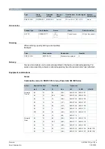
Страница 3: ...tory or ordered separately For easier valve assembly actuators ordered separately have the actuator stem fully retracted Equipment combinations Valves Combinable valves for SSB161 05U 2 way Powermite 599 MZ Series Action Nominal Line Size Flow Rate Connection Inch mm Cv Kvs FxF FxUM AFxUM Normally Closed 0 5 15 0 4 0 34 599 01100 599 01101 0 5 15 0 63 0 54 599 01102 599 01103 0 5 15 1 0 0 85 599 0...

Страница 4: ... documentation Topic Title Document ID Installation Mounting instruction A6V13122037 Standards and directives CE declarations A5W00254962A RCM conformity A5W00254983A Environmental compatibility Environmental declarations A5W00242127A Related documents such as the environmental declarations CE declarations etc can be downloaded from the following Internet address www siemens com bt download Notes ...

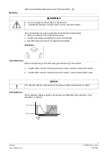
Страница 5: ...en the union nut manually See Mounting instructions for graphical instructions Orientation Commissioning When commissioning check both wiring and functioning of the actuator Actuator stem extends Normally open valve closes normally closed valve opens Actuator stem retracts Normally open valve opens normally closed valve closes NOTICE The actuator must be commissioned only with a correctly mounted ...

Страница 6: ...low for at least three seconds The actuator ignores any control signal from the controller 3 Adjust the position of the actuator stem by rotating hexagonal wrench b illustrated below clockwise or counter clockwise The actuator stem moves down if you rotate clockwise it moves up if you rotate counter clockwise The manually set position is retained 4 To exit manual operation mode press and hold down...

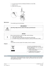
Страница 7: ...ns from the terminals The actuator must be commissioned only with a correctly mounted valve in place Repair The actuators cannot be repaired the complete unit must be replaced Disposal The device is considered an electronic device for disposal and may not be disposed of as domestic waste Dispose of the device through channels provided for this purpose Comply with all local and currently applicable...

Страница 8: ...evices use Open Source Software OSS All Open Source Software components used in the product to include copyrights and licensing agreement are available at http siemens com bt download Firmware version OSS document Device Document ID Title 2 10 0 or above A6V13503690 Readme OSS for Modulating Room Actuator 200N 300N All ...

Страница 9: ...contact Y See Technical design 2 Running speed time for 5 5 mm 5 s mm 25 27 5 s 25 Positioning force 45 lbf 200 N Stroke 0 05 to 0 25 inch 1 2 6 5 mm Permissible temperature of medium in the connected valve 34 to 248 F 1 120 Electrical connection Permissible length for signal lines 65 ft 20 m Wire cross section 18 20 AWG 0 5 0 75 mm Cable diameter 0 2 inch 5 mm Mounting Connection to valve Plastic...

Страница 10: ...e that interference will not occur in a particular installation If this equipment does cause harmful interference to radio or television reception which can be determined by turning the equipment off and on the user is encouraged to try to correct the interference by one or more of the following measures Reorient or relocate the receiving antenna Increase the separation between the equipment and r...

Страница 11: ...11 Siemens A6V12681516_enUS_a Smart Infrastructure 10 12 2022 Material Cover base PC ABS Weight 7 8 ounces 220 g ...

Страница 12: ...ntrol signal DC 0 10 V G System potential AC DC 24 V Connection diagrams N Controller Y Actuator SP G System potential AC 24 V SN G0 System neutral Y Control signal Dimensions mm inch Revision numbers Type Valid from rev no SSB161 05U A G Y G0 Y SN AC 24 V DC 24 V 2AF 76 7 3 27 7 1 1 92 6 3 7 A6V12681511Z15 49 1 9 ...

Страница 13: ......

Страница 14: ... Global Headquarters Theilerstrasse 1a CH 6300 Zug 41 58 724 2424 www siemens com buildingtechnologies Siemens Switzerland Ltd 2022 Technical specifications and availability subject to change without notice Document ID A6V12681516_enUS_a Edition 10 12 2022 ...

Отзывы: