8BCOMMUNICATION WITH OTHER SYSTEMS
Status is the same as bit 6 in Task Controlling (output byte 3 for channel 1 or
output byte 11 for channel 2), then SIWAREX U has synchronized the live bit.
In Task Controlling, the live bit must now be inverted. SIWAREX U will in turn set
the same status for the live bit in Status.
If this does not occur within a certain period, the component/communication has
failed. The period at the end of which a component is deemed to have failed can
be specified using the user program.
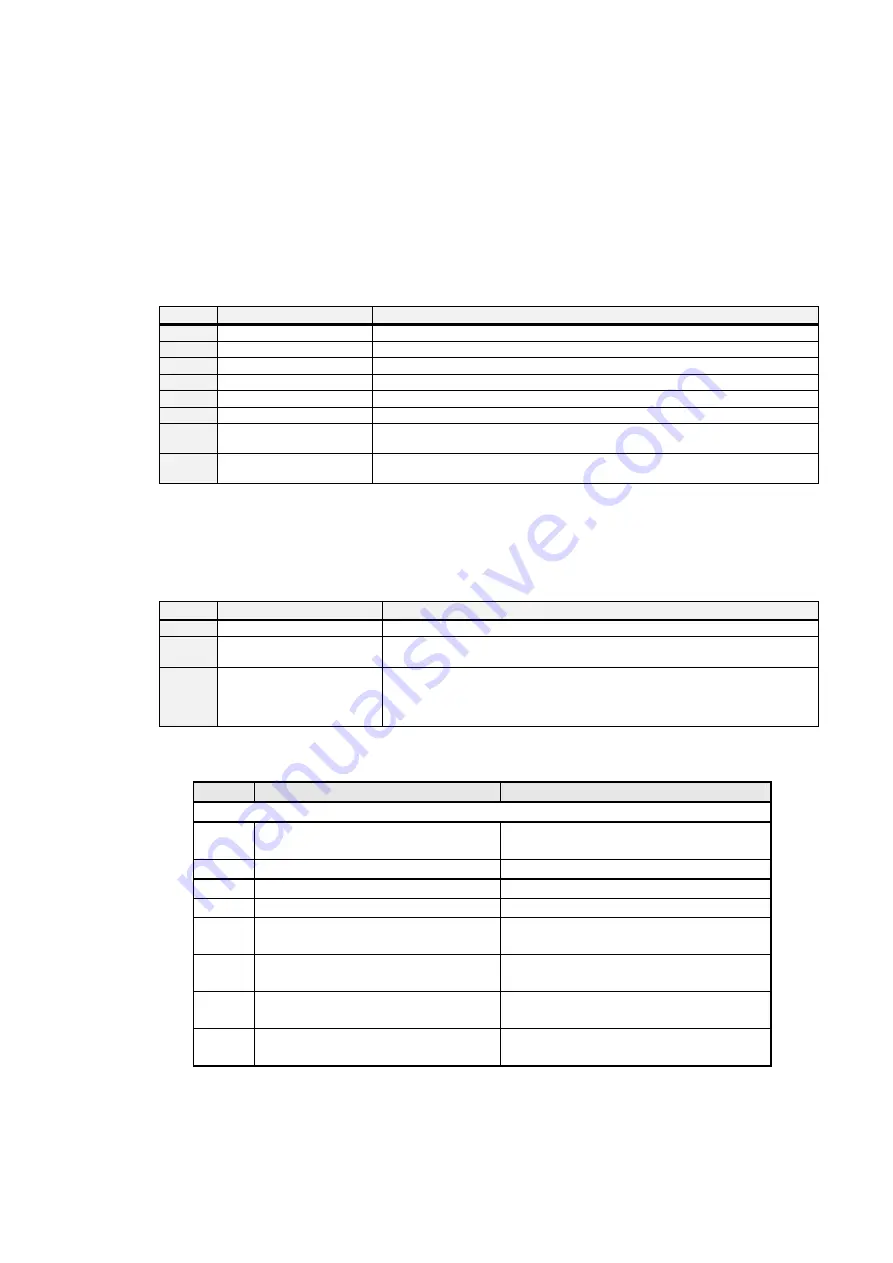
Bit_no.
Name
Range of values/Meaning
0
Operational fault
1 = an operational fault exists
1
Data, operator errors
1 = during the last action, a data or operator error occurred.
2
Limit value 1 active
1 = limit value 1 is activated
3
Limit value 2 active
1 = limit value 2 is activated
4
Adjusted
1 = scale is already adjusted
5
Measured value toggle bit
Measured value toggle bit is inverted with each new measured value (every 20 ms).
6
Live bit
The live bit is specified by the user in the output area and is synchronized in the
input area (I/O communication only).
7 Instruction
acknowledgement
The instruction bit is inverted after the execution of an instruction (I/O
communication only).
Table 9-1
Content of the status byte
Bit 7 in the status byte (input byte 1 for channel 1 and input byte 9 for channel 2) is
used to process the writing to SIWAREX U together with the instruction bit of the byte
for task controlling (output byte 3 for channel 1 and output byte 11 for channel 2).
Bit_no.
Name
Range of values/Meaning
0-5 Reserve
6
Live bit
The live bit is specified by the user in the output area and is synchronized in
the input area (I/O communication only).
7
Instruction bit
The user must check the instruction bit for consistency in the input area. A new
instruction is executed when this bit is changed and the bit "Instruction
acknowledgement" follows this change in the input area
(I/O communication only).
Table 9-2
Byte for task controlling
Byte
S7 output area
S7 input area
Channel 1
0
Number n for reading DR(n) and DR(n+1)
Confirmation of number n for DR(n) and
DR(n+1) prepared for reading
1
Number m for writing DR(m)
Status byte
2
Reserved
Current weight (H) (updated cyclically)
3
Task controlling
Current weight (L) (updated cyclically)
4
Variable (H) of DR(m) for writing
Current variable (H) corresponding to data
record number n
5
Variable (L) of DR(m) for writing
Current variable (L) corresponding to data
record number n
6
Default value for remote display 1 (H)
(transferred cyclically)
Current variable (H) corresponding to data
record number n+1
7
Default value for remote display 1 (L)
(transferred cyclically)
Current variable (L) corresponding to data
record number n+1
SIWAREX U
9-59


