The Transducer Block
3.5 AI_Transducer Block Configuration Flowchart
SITRANS TH400 PROFIBUS® PA Configuration Manual, 02/2007, A5E01039143-01
13
3.5
AI_Transducer Block Configuration Flowchart
Страница 1: ...n 1 The Physical Block PA Slot 0 PROFIBUS 2 The Transducer Block 3 Analogue Input Blocks PROFIBUS 4 SITRANS T Temprature measuring instruments SITRANS TH400 PROFIBUS PA Configuration Manual 02 2007 A5E01039143 01 ...
Страница 2: ...ation Commissioning and operation of a device system may only be performed by qualified personnel Within the context of the safety notes in this documentation qualified persons are defined as persons who are authorized to commission ground and label devices systems and circuits in accordance with established safety practices and standards Prescribed Usage Note the following Warning This device may...
Страница 3: ...urement of RTD with two sensors 16 3 6 3 Measurement of thermocouple with one sensor 16 3 6 4 Measurement of thermocouple with two sensors 17 3 6 5 Measurement of combined sensors Sensor 1 TC and Sensor 2 RTD 18 3 6 6 Measurement of resistance linear with one sensor 18 3 6 7 Measurement of resistance linear with two sensors 19 3 6 8 Measurement of potentiometer linear with one sensor 19 3 6 9 Meas...
Страница 4: ... 33 3 8 8 Sensor calibration Description 34 3 8 9 Sensor Calibration Parameters 35 3 9 PR_CUST_LIN Block PA Slot 4 Parameter List 36 3 9 1 Linear interpolation linearisation Description 36 3 9 2 Linear Interpolation Linearisation Parameter List 36 3 9 3 Custom Polynomial Linearisation Description 39 3 9 4 Custom Polynomial Linearisation Parameter List 40 3 10 PR_CUST_PRIV Block PA Slot 5 Reserved ...
Страница 5: ...system SIMATIC PDM requires the device specific device data file GSD and the Device Description Language file DDL If you want to use SITRANS TH400 PA in other host systems you can find the GSD file and DDL files on the CD SITRANS T transmitter for temperature A5E00364512 which may be ordered separately On the Internet http www siemens com sitranst Parameter lists abbreviations In the Store column ...
Страница 6: ...need more information or have particular problems which are not covered sufficiently by the operating instructions contact your local Siemens Regional Office You will find the address of your local Siemens Regional Office on the Internet Product information on the Internet The Programming Manual is an integral part of the companion CD which may be ordered separately In addition the Programming Man...
Страница 7: ...interface there are diagnosis parameters in the device The diagnosis parameters have a bit string data type and there is a mask parameter indicating which diagnosis is supported by the device 2 2 Diagnosis of the Device Characteristics In the Physical block the DIAGNOSIS parameter has the information about the alerts into the device for instance device not initialized power up factory init hardwar...
Страница 8: ...fic ALARM_SUM 7 Current state of the blocks alarms DS 42 D 8 RO 0 0 0 0 SOFTWARE_REVISION 8 Software revision of the device VISBLE_ STRING Cst 16 RO HARDWARE_REVISION 9 Physical revision of the device VISBLE_ STRING Cst 16 RO DEVICE_MAN_ID 10 Siemens AG manufacturer identification number Unsigned 16 Cst 2 RO 0x006D DEVICE_ID 11 Manufacturer device number VISBLE_ STRING Cst 16 RO SITRAN S TH400 DEV...
Страница 9: ...x Description Type Store Size R W Min Max Default DEVICE_INSTAL_DATE 22 Date of the device installation OCTET_ STRING SRC 16 R W LOCAL_OP_ENA 23 Not Used Unsigned 8 N 1 R W 1 IDENT_NUMBER_ SELECT 24 0 Profile specific Ident_Number 1 Manufacture specific Ident_Number Unsigned 8 SRC 1 R W 1 HW_WRITE_PROTECTI 25 Unimplemented reserved 26 32 Reserved to PNO PROFIBUS Nutzerorganisation ...
Страница 10: ...fine how the SITRANS TH400 Transmitter functions Selections such as setting of input type engineering units defining the dual functionality when using the dual input and so forth are performed in the Transducer Block The transducer block in SITRANS TH400 allows the user to select a large number of sophisticated functions Therefore the configuration of the transmitter must be carried out with the g...
Страница 11: ... chapter 3 8 3 Output conditioning parameters chapter 3 8 4 Output parameters chapter 3 8 5 Diagnostic parameters chapter 3 8 6 Sensor error detection parameters chapter 3 8 7 Sensor calibration parameters chapter 3 8 9 PR_CUST_LIN Block chapter 3 9 Linear Interpolation Linearisation chapter 3 9 2 Custom Polynomial linearisation chapter 3 9 4 PR_CUST_PRIV Block chapter 3 10 PR_CUST_PRIV Block chap...
Страница 12: ... C chapter 3 8 1 PRIMARY_VALUE_UNIT value 1001 3 wire connection chapter 3 8 2 SENSOR_CONNECTION value 1 Only sensor 1 chapter 3 8 4 SENSOR_MEAS_TYPE value 220 No sensor error detection chapter 3 8 7 SENSOR_WIRE_CHECK_1 value 3 3 4 Your application set up In the Transducer block all parameters marked R W can be adapted to suit any measurement in temperature ohm or mV The way of presenting the file...
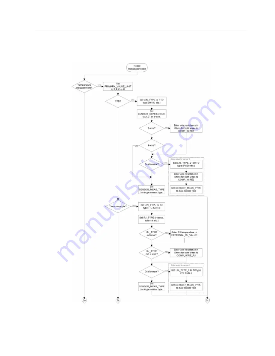
Страница 13: ...The Transducer Block 3 5 AI_Transducer Block Configuration Flowchart SITRANS TH400 PROFIBUS PA Configuration Manual 02 2007 A5E01039143 01 13 3 5 AI_Transducer Block Configuration Flowchart ...
Страница 14: ...ter wire resistance in Ohms for both wires to COMP_WIRE1 2 wire YES Enter setup for sensor 2 YES Set LIN_TYPE_2 to no linearisation or linearisation table Set SENSOR_MEAS_TYPE to single sensor type Set LIN_TYPE to no linearisation or linearisation table to dual sensor type Enter wire resistance in Ohms for both wires to COMP_WIRE2 Millivolts Set to V mV or µV Set LIN_TYPE to no linearisation or li...
Страница 15: ...etup for sensor 2 YES Set LIN_TYPE_2 to no linearisation or linearisation table Set to single sensor type Set LIN_TYPE to no linearisation or linearisation table to dual sensor type Enter wire resistance in Ohms for 2 wires to COMP_WIRE2 Error try again Finished Transducer block is configured Enter Custom RTD polynomial values Linearisation table Custom RTD Enter linearisation table values YES YES...
Страница 16: ... 4 wire SENSOR_CONNECTION_2 N A ignored in setup check RJ_TYPE N A ignored in setup check Connections RTD 2 Wire RTD 3 wire RTD 4 wire 3 6 2 Measurement of RTD with two sensors PRIMARY_VALUE_UNIT K C F or R LIN_TYPE Any RTD LIN_TYPE_2 Any RTD SENSOR_MEAS_TYPE Anything but not PV SV_1 SV_2 not available SENSOR_CONNECTION 2 or 3 wire SENSOR_CONNECTION_2 Default set to 2 wire RJ_TYPE N A ignored in s...
Страница 17: ...ternal External constant value Sensor 2 wire or Sensor 3 wire Connections TC internal CJC TC 2 wire external CJC TC 3 wire external CJC 3 6 4 Measurement of thermocouple with two sensors PRIMARY_VALUE_UNIT K C F or R LIN_TYPE Any TC LIN_TYPE_2 Any TC SENSOR_MEAS_TYPE Anything but not PV SV_1 SV_2 not available SENSOR_CONNECTION N A ignored in setup check SENSOR_CONNECTION_2 N A ignored in setup ch...
Страница 18: ...PE No Reference Junction Internal External constant value Connections Sensor 1 TC Sensor 2 RTD 2 wire Sensor 1 TC Sensor 2 RTD 3 wire Connections with two sensors can be configured for 2 measurements difference average or redundancy 3 6 6 Measurement of resistance linear with one sensor PRIMARY_VALUE_UNIT Ohm or kOhm LIN_TYPE No linearisation LIN_TYPE_2 N A ignored in setup check SENSOR_MEAS_TYPE ...
Страница 19: ...ECTION_2 Default set to 2 wire RJ_TYPE N A ignored in setup check Connections Resistance 2 wire Resistance 2 3 wire 1 2 1 2 Connections with two sensors can be configured for 2 measurements difference average or redundancy 3 6 8 Measurement of potentiometer linear with one sensor PRIMARY_VALUE_UNIT LIN_TYPE No linearisation LIN_TYPE_2 N A ignored in setup check SENSOR_MEAS_TYPE PV SV_1 SV_2 not av...
Страница 20: ...t to 3 wire SENSOR_CONNECTION_2 Default set to 3 wire RJ_TYPE N A ignored in setup check Connections 2 x 3 wire Potmeters Connections with two sensors can be configured for 2 measurements difference average or redundancy 3 6 10 Measurement of voltage linear with one sensor PRIMARY_VALUE_UNIT µV mV or V LIN_TYPE No linearisation LIN_TYPE_2 N A ignored in setup check SENSOR_MEAS_TYPE PV SV_1 SV_2 no...
Страница 21: ... measurements difference average or redundancy 3 6 12 Measurement of 2 potentiometers with Linear interpolation linearisation PRIMARY_VALUE_UNIT LIN_TYPE Table Linearisation LIN_TYPE_2 Table Linearisation same table as sensor 1 SENSOR_MEAS_TYPE Anything but not PV SV_1 SV_2 not available SENSOR_CONNECTION Default set to 3 wire SENSOR_CONNECTION_2 Default set to 3 wire RJ_TYPE N A ignored in setup ...
Страница 22: ...garithmic potentiometer to a linear signal TAB_ACTUAL_NUMBER 10 number of linearisation points to follow up to max 50 TAB_XY_VALUE1 0 0 100 TAB_XY_VALUE2 0 1 0 TAB_XY_VALUE3 0 2 100 TAB_XY_VALUE4 0 4 200 TAB_XY_VALUE5 0 8 300 TAB_XY_VALUE6 1 6 400 TAB_XY_VALUE7 3 2 500 TAB_XY_VALUE8 6 4 600 TAB_XY_VALUE9 12 8 700 TAB_XY_VALUE10 25 6 800 Output will readout 325 with 1 0 potentiometer value ...
Страница 23: ...YPE No Reference Junction Internal External constant value or Sensor 2 wire or Sensor 3 wire Connections TC internal CJC TC 2 wire external CJC TC 3 wire external CJC Now enter the Custom TC parameters in PR_CUST_LIN Block PA Slot 4 See 3 9 4 Custom Polynomial Linearisation Parameter List for further details Remember to enter values for the RJ polynomial if RJ_TYPE is any value other than No refer...
Страница 24: ...50E 11 1 41E 7 2 26E 2 4 18 CUSTOM_TC_POLY_4 30000 0 3 49E 18 2 19E 12 1 53E 7 2 68E 2 9 26 CUSTOM_TC_POLY_5 70000 0 6 27E 17 8 76E 12 5 34E 7 8 69E 3 1 65E2 3th degree coefficient 2th degree coefficient 1st degree coefficient 0 degree coefficient CUSTOM_TC_RJ_POLY 1 11E 4 2 65E 2 3 94E1 3 94E 1 A TC input of 5000 µV and an RJ temperature of 25ºC will make POLY_3 the active and the output will be ...
Страница 25: ...IN LIN RJ_TEMP none Arithmetic redund SECONDARY_VALUE_1 SECONDARY_VALUE_2 PRIMARY_VALUE SENSOR_MEAS_TYPE BIAS_1 BIAS_2 LIN LIN_TYPE_1 2 SENSOR_CONNECTION_1 2 COMP_WIRE_1 2 Process calibration Min Max hold min max min max MIN_SENSOR_VALUE_1 2 MAX_SENSOR_VALUE_1 2 RTDX_FACTOR_1 2 CAL_POINT_HI_1 2 CAL_ACTUAL_HI_1 2 CABLE_RES1 2 RJ RJ_COMP_WIRE SENSOR_WIRE_CHECK_1 2 SENSOR_WIRE_CHECK_RJ CUSTOM_TC_ TAB...
Страница 26: ...C 60751 102 RTD Pt100 a 0 003850 IEC 60751 103 RTD Pt200 a 0 003850 IEC 60751 104 RTD Pt500 a 0 003850 IEC 60751 105 RTD Pt1000 a 0 003850 IEC 60751 106 RTD Pt10 a 0 003916 JIS C1604 81 107 RTD Pt50 a 0 003916 JIS C1604 81 108 RTD Pt100 a 0 003916 JIS C1604 81 122 RTD Ni50 a 0 006180 DIN 43760 123 RTD Ni100 a 0 006180 DIN 43760 124 RTD Ni120 a 0 006180 DIN 43760 125 RTD Ni1000 a 0 006180 DIN 43760...
Страница 27: ...and input range The unit of UPPER_SENSOR_LIMIT is the PRIMARY_VALUE_UNIT Float N 4 RO 850 LOWER_SENSOR_LIMIT 22 Physical lower limit function of sensor1 e g Pt 100 200 C and input range The unit of LOWER_SENSOR_LIMIT is the PRIMARY_VALUE_UNIT Float N 4 RO 200 LOWER_SENSOR_ LIMIT_2 63 Physical lower limit function of sensor2 e g Pt 100 200 C and input range The unit of LOWER_SENSOR_LIMIT is the PRI...
Страница 28: ...ne resistance when Sensor 2 is a resistive sensor connected with 2 wires Float SRC 4 R W 0 100 0 SENSOR_ CONNECTION_2 62 Connection to sensor 2 select for 2 3 and 4 wire connection Ignored if sensor 2 is not a resistive sensor Defined codes 0 2 wires 1 3 wires Unsigned 8 SRC 1 R W 0 CABLE_RES1 87 For 3 or 4 wire resistance measurements Indicates the measured cable resistance in the wire connected ...
Страница 29: ...n temperature is measured by the device itself via an internally mounted sensor 2 External The fixed value EXTERNAL_RJ_ VALUE is used for compensation The reference junction must be kept at a constant temperature e g by a reference junction thermostat 3 Sensor 2 w Reference junction temperature is measured by external 2 wire con nected Pt100 sensor 4 Sensor 3 w Reference junction temperature is me...
Страница 30: ...vely related to Sensor 2 are not available and no alarms will be generated for Sensor 2 221 PV SV_1 but SV_2 if SV_1 is wrong INPUT_FAULT_1 0 222 PV SV_2 but SV_1 if SV_2 is wrong INPUT_FAULT_2 0 Unsigned 8 SRC 1 R W 220 BIAS_1 19 Bias that can be algebraically added to process value of sensor 1 SV1 The unit of BIAS_1 is the PRIMARY_VALUE_UNIT Float SRC 4 R W 0 BIAS_2 20 Bias that can be algebraic...
Страница 31: ...annel 280 DS 33 D 5 RO 0 SECONDARY_VALUE_1 10 Process value connected to sensor 1 corrected by BIAS_1 The unit of SECONDARY_VALUE_1 is the PRIMARY_VALUE_UNIT FF Channel 2 Output PA Channel 282 DS 33 D 5 RO 0 SECONDARY_VALUE _2 11 Process value connected to sensor 2 corrected by BIAS_2 The unit of SECONDARY_VALUE_2 is the PRIMARY_VALUE_UNIT FF Channel 3 Output PA Channel 283 DS 33 D 5 RO 0 INTERN_T...
Страница 32: ... 0 underrange 1 overrange 2 lead breakage 3 short circuit 4 5 reserved 6 7 manufacturer specific Unsigned 8 D 1 RO 0 INPUT_FAULT_2 26 Input malfunction Diagnosis object for errors that concern SV_2 0 Input OK Bit definition see INPUT_FAULT_1 Unsigned 8 D 1 RO 0 RJ_FAULT 67 Input malfunction Diagnosis object for errors that concern RJ sensor 0 Input OK Bit 0 underrange 1 overrange 2 lead breakage 3...
Страница 33: ...id values 0 Lead breakage and short circuit detection enable 1 Lead breakage detection enable short circuit detection disable 2 Lead breakage detection disable short circuit detection enable 3 Lead breakage and short circuit detection disable Unsigned 8 SRC 1 R W 3 SENSOR_WIRE_CHECK_2 28 Enables lead breakage and short circuit detection for Sensor 2 Valid values see SENSOR_WIRE_CHECK_1 Unsigned 8 ...
Страница 34: ...Factory trim Standard 103 The sensor calibration function in SITRANS TH400 will change the slope of the linarisation curve so the curve is adjusted to the connected sensor To obtain accurate temperature measurement in the range e g 0 100 C apply to the sensor a temperature e g of 5 C as the low temperature and e g 95 C as the high temperature through a precise temperature calibrator At sensor cali...
Страница 35: ...2 R W SENSOR_CAL_DATE_1 76 The last date on which the calibration was performed 7 Unsigned 8 SRC 7 R W 0 0 0 0 1 1 103 SENSOR_CAL_WHO_1 77 The name of the person responsible for the last sensor calibration OCTET_ STRING SRC 32 R W CAL_POINT_LO_2 78 The low calibration value applied to sensor 2 The value from either a calibrator or a reference equipment Float SRC 4 R W 1038 CAL_ACTUAL_LO_2 79 Enter...
Страница 36: ... mV is connected to input 3 9 2 Linear Interpolation Linearisation Parameter List Parameter Rel Index PA Description Type Store Size byte RO R W Min Max Default TAB_MIN_NUMBER 29 Minimum number of linearisation points allowed 10 Unsigned 8 N 1 RO 10 TAB_MAX_NUMBER 30 Maximum number of linearisation points allowed 50 Unsigned 8 N 1 RO 50 TAB_ACTUAL_NUMBER 31 Number of linearisation points in the li...
Страница 37: ...51 Linearisation x y coordinate 20 Float array SRC 8 R W 0 0 TAB_X_Y_VALUE21 52 Linearisation x y coordinate 21 Float array SRC 8 R W 0 0 TAB_X_Y_VALUE22 53 Linearisation x y coordinate 22 Float array SRC 8 R W 0 0 TAB_X_Y_VALUE23 54 Linearisation x y coordinate 23 Float array SRC 8 R W 0 0 TAB_X_Y_VALUE24 55 Linearisation x y coordinate 24 Float array SRC 8 R W 0 0 TAB_X_Y_VALUE25 56 Linearisatio...
Страница 38: ...inearisation x y coordinate 40 Float array SRC 8 R W 0 0 TAB_X_Y_VALUE41 72 Linearisation x y coordinate 41 Float array SRC 8 R W 0 0 TAB_X_Y_VALUE42 73 Linearisation x y coordinate 42 Float array SRC 8 R W 0 0 TAB_X_Y_VALUE43 74 Linearisation x y coordinate 43 Float array SRC 8 R W 0 0 TAB_X_Y_VALUE44 75 Linearisation x y coordinate 44 Float array SRC 8 R W 0 0 TAB_X_Y_VALUE45 76 Linearisation x ...
Страница 39: ... a customer specific polynomial linearisation The function is primarily suitable for specific thermo elements but also for millivolt signals if the user can accept to enter the input and the output values of the polynomial in µV and C respectively LIN_TYPE 241 Custom defined RTD generates a customer specific polynomial linearisation The function is particularly suitable for specific RTD sensors bu...
Страница 40: ... Polynomial part 4 of Custom defined TC converting µV to C Consisting of maximum input value in µV a4 a0 polynomial coefficients 6 Float SRC 24 R W 120000 0 0 0 0 01 0 CUSTOM_TC_POLY_5 17 Polynomial part 5 of Custom defined TC converting µV to C Consisting of maximum input value in µV a4 a0 polynomial coefficients 6 Float SRC 24 R W 150000 0 0 0 0 01 0 CUSTOM_TC_RJ_POLY 18 RJ Polynomial part of cu...
Страница 41: ...of Custom defined RTD converting Ohm to C Consisting of maximum input value in Ohms a4 a0 polynomial coefficients 6 Float SRC 24 R W 8000 0 0 0 0 01 0 CUSTOM_RTD_POLY_5 28 Polynomial part 5 of Custom defined RTD converting Ohm to C Consisting of maximum input value in Ohms a4 a0 polynomial coefficients 6 Float SRC 24 R W 10000 0 0 0 0 01 0 3 10 PR_CUST_PRIV Block PA Slot 5 Reserved Parameter List ...
Страница 42: ...The Transducer Block 3 10 PR_CUST_PRIV Block PA Slot 5 Reserved Parameter List SITRANS TH400 PROFIBUS PA 42 Configuration Manual 02 2007 A5E01039143 01 ...
Страница 43: ...ocks Overview PROFIBUS Analog Input Function Blocks represent transmitters The parameters are shown in Figure 1 Function Block Analog Input Standard Parameters ProcessParameters Alarm Parameters ALARM_HYS LO_LO_ALM OUT CHANNEL PV_SCALE OUT_SCALE PV_FTIME SIMULATE Figure 1 Summary of the parameter of Analog Input Function Blocks ...
Страница 44: ...ucture of the MODE and the simulation feature of the AI is shows in Figure 2 Figure 2 Simulation Mode and Status diagram of Analog Input Function Block The structure of the AI with Simulation Mode and Status is shown in Figure 2 More details about the relationships between the AI parameters are visible in Figure 3 Figure 3 Parameter relationship of AI FB ...
Страница 45: ...le state PV_SCALE 11 Conversion of the Process Variable into percent using the high and low scale values The engineering unit of PV_SCALE high and low scale values are directly related to the PV_UNIT of the configured Transducer Block configured via Channel parameter The PV_SCALE high and low scale values follow the changes of the PV_UNIT of the related Transducer Block automatically i e a change ...
Страница 46: ...per limit of alarms DS 39 D 16 RO 0 HI_ALM 31 State of the upper limit of warnings DS 39 D 16 RO 0 LO_ALM 32 State of the lower limit of warnings DS 39 D 16 RO 0 LO_LO_ALM 33 State of the lower limit of alarms DS 39 D 16 RO 0 SIMULATE 34 For commissioning and test purposes the input value from the Transducer Block in the Analogue Input Function Block AI FB can be modified This means that the Trans...
Страница 47: ......
Страница 48: ......