4.6.2
Connecting the SITRANS TF320 dual chamber housing
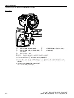
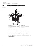
Procedure
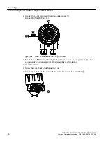
5
+$57
①
Supply voltage
⑤
Input terminals
②
HART communication resistor (optional)
⑥
Protective conductor connector
③
Cable gland
⑦
Ground terminal
④
Test terminals
Figure 4-2
Connecting the device
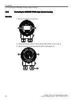
1. Lead the shielded connecting cables through the cable glands
③
.
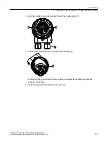
2. Connect the device to the plant with the protective conductor connection
⑥
.
3. Connect the wires of the power supply
①
to the terminals (+) and (-).
Take the polarity into account. The device has reverse polarity protection.
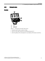
4. Connect the shield to the screw of the ground terminal
⑦
.
The screw of the ground terminal is electrically connected to the external protective
conductor connection.
Connecting
4.6 Connecting the SITRANS TF dual chamber housing
SITRANS TH320/TH420/TR320/TR420/TF320/TF420
40
Compact Operating Instructions, 03/2018, A5E41865021-AA


