Typical circuits
A.1 Typical circuits for 3RM1
SIRIUS 3RM1 motor starter
Manual, 06/2016, A5E0345285095020A/RS-AE/005
169
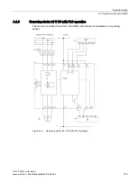
A.1.3
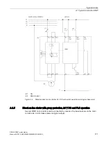
Direct-on-line starter 24 V DC with switch operation and 400 V brake
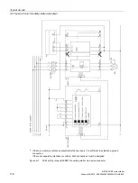
The current for the brake facility is drawn via two phases. Connection is via T1 and T3.
Make allowance for the additional current in the current setting value.
The configuration is shown based on the example of a standard motor starter. The
configuration with a 400 V brake is also admissible for the Failsafe variants 3RM11 and
3RM13. The notes on safety-related shutdown (Page 174) must be observed.
-S1 ON
-S2 Remote reset
Figure A-3 Standard 24 V DC direct-on-line starter with switch operation and 400 V brake


