Data in the Modbus registers
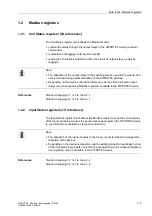
1-6
SIPROTEC Modbus - Bus mapping 7UM62
C53000-L1840-C009-03
1.2.3
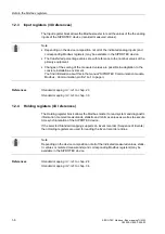
Input registers (3X references)
The Input register block allows the Modbus master to read the values of the the analog
inputs of the SIPROTEC device (recorded measured values).
References
Standard mapping 3-1: ref. to chap. 2.3
Standard mapping 3-2: ref. to chap. 3.3
1.2.4
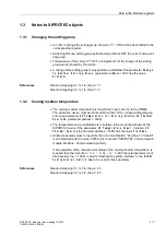
Holding registers (4X references)
The Holding register block allows the Modbus master to read system and diagnostic
information, metered measurands, statistic and min/max values as well as to execute
time synchronization of the SIPROTEC device.
If the selected Standard mapping supports an Event recorder (Sequence of Events)
then Holding registers are used for reading the Event recorder entries.
References
Standard mapping 3-1: ref. to chap. 2.4
Standard mapping 3-2: ref. to chap. 3.4
Note:
•
Depending on the device composition not all of the indicated analog inputs (and
corresponding Modbus registers) may be available in the SIPROTEC device.
•
The transferred percentage values are with reference to the nominal values of the
primary equipment.
•
Changes of the scaling of the measured values are possible in adaptation to the
concrete installation enviroment.
You find information about this in the manual "SIPROTEC Communication module,
Modbus - Communication profile" (ref. to page i).
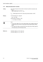
Note:
Depending on the device composition not all of the indicated measured values, statis-
tic values or metered measurands (and corresponding Modbus registers) may be
available in the SIPROTEC device.
Содержание SIPROTEC4 7UM62
Страница 6: ...Preface iv SIPROTEC Modbus Bus mapping C53000 L1840 C009 03 ...
Страница 8: ...Revision index vi SIPROTEC Modbus Bus mapping C53000 L1840 C009 03 ...
Страница 12: ...Table of contents x SIPROTEC Modbus Bus mapping C53000 L1840 C009 03 ...
Страница 58: ...Standard mapping 3 2 3 20 SIPROTEC Modbus Bus mapping 7UM62 C53000 L1840 C009 03 ...
Страница 60: ...Glossary 4 2 SIPROTEC Modbus Bus mapping C53000 L1840 C009 03 ...


