


Manual 7SJ46
Settings
C53000-K1174-C002-4
52
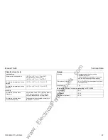
All parameters are set on an additive basis. Some parameters
have fixed upper and lower thresholds.
If you set a value below the minimum setting, the minimum
setting applies.
If you set a value above the maximum setting, the maximum
setting applies.
Parameters marked with "
∞
" allow to deactivate the associated
protection stage. To do so, set all switches to "on" position.
The setting ranges for the parameters can be found in the
Technical Data (2.11) or on the indications on the front panel.
Ip
120A
100A
--------------
I
NS
I
N
--------
1
⋅
25
,
⋅
1 5 I
N
⋅
,
=
=
.
.
Setting value
,
Switch values
,
å
=
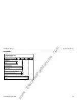
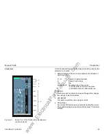
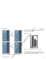
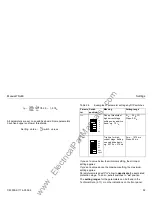
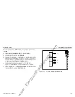
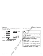
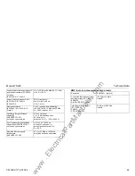
Table 2-3
Examples of parameter settings by DIP switches
Parame
ter
Switch
position
Meaning
Setting range
I>>
Pick-up threshold of
high-current stage,
setting on an additive
basis, e.g. 7.5 I
N
2 I
N
... 20 I
N
;
∞
Steps: 0.5 I
N
T I>>
Trip time for high-
current stage, setting
on an additive basis,
e.g. 0.275 s = 275 ms
0 ms ... 1575 ms
Steps: 25 ms
16
8
4
2
1
0,5
0.8
0.4
0.2
0.1
0.05
0.025
www
. ElectricalPartManuals
. com