


Manual 7SJ46
Construction
C53000-K1174-C002-4
46
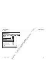
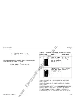
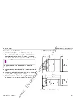
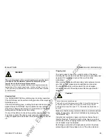
Front view
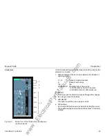
Figure 2-1
Device front of the 7SJ46 with indication and
control elements
On the front panel (Figure 2-1) the following indication and control
elements are located:
1. LEDs to indicate process or device status and indication of
operating states
L1...L3
Pickup of individual phases
N
Pickup of earth stage
Trip
Trip
RUN/ERROR Operating state of the device.
- In ”RUN” state the LED shines green.
- In ”ERROR” state the LED shines red.
2. ENTER
This key is used to activate the device settings, after changing
the settings of the DIP switches.
3. LED-RESET
This button resets the pickup indicator LEDs.
4. DIP switches
Five 6-pole DIP switches are provided for setting the device.
The possible settings are described in the section “Parameter
settings”.
SIPROTEC
7SJ4
-
123456
ON
60 Hz
50 Hz
FREQ.
IE
I>>
MODE
M INV
V INV
E INV
ANSI 51
DT O/C
50/51
123456
123456
1
2
3456
ON
123456
ON
ON
ON
8
4
2
1
0.5
0.25
3.2
1.6
0.8
0.4
0.2
0.1
TI>
MIN 0
MAX 6.3
D
MIN 0.5
MAX 15
[s]
3.2
1.6
0.8
0.4
0.2
0.1
3.2
1.6
0.8
0.4
0.2
0.1
I>
MIN 0.5
MAX 6.2/
Ip
MIN 0.5
MAX 4/
[I/I ]
N
0.8
0.4
0.2
0.1
0.05
0.025
TI>>
MIN 0
MAX 1.575
[s]
0.8
0.4
0.2
0.1
0.05
0.025
TI>>
MIN 0
MAX 1.575
16
8
4
2
1
0.5
I>>
MIN 2
MAX 20/
[I/I ]
N
16
8
4
2
1
0.5
I>>
MIN 2
MAX 20/
.
.
.
.
NOT STORED
STORED
LED´S
TRIP
L1
L3
L2
N
ENTER
RUN/ERROR
LED
RESET
1
2
3
SW1
SW2
SW3
SW4
SW5
4
www
. ElectricalPartManuals
. com