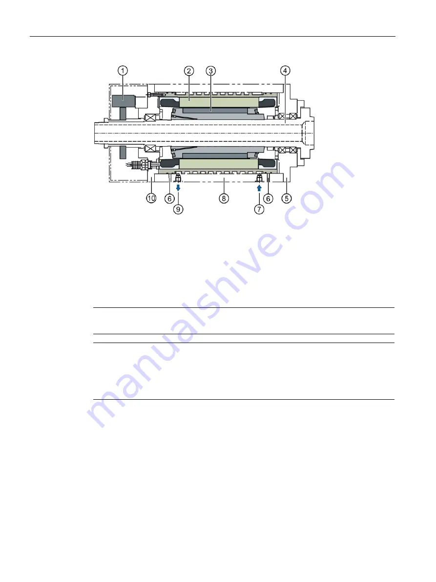
Description
2.2 Features and system preconditions
SIMOTICS M-1FE1 synchronous built-in motors
24
Configuration Manual, 09/2019, A5E47872980B AA
1 Encoder
6
Leakage drain bore
2 Stator with cooling jacket
7
Cooling water connection intake
3 Rotor with sleeve
8
Spindle housing
4 Spindle shaft with bearings
9
Cooling water connection outlet
5 DE bearing shield (DE = Drive End)
10 NDE bearing shield (NDE = non drive
end)
Figure 2-2 Motor spindle design
Note
It is not permissible that the bearing shield protrudes into the motor installation space
Note
The spindle manufacturer is responsible for designing the bearings, lubrication and
cooling.
A non-permanent (soft) magnetic shaft material is required to achieve the electrical
parameters.
Magnetic attraction
Forces of attraction occur between the rotor and stator in electric motors as a result of
the magnetic principle.
The surrounding mechanical structure must absorb these forces.
●
The surrounding mechanical structure (spindle shaft, bearings, spindle housing)
should be designed to be as stiff as possible so that no vibration can occur.
Содержание Simotics M-1FE1 Series
Страница 1: ...SIMOTICS M 1FE1 synchronous built in motors ...
Страница 2: ......
Страница 12: ...Table of contents SIMOTICS M 1FE1 synchronous built in motors 10 Configuration Manual 09 2019 A5E47872980B AA ...
Страница 22: ......
Страница 46: ......
Страница 52: ......
Страница 78: ......
Страница 82: ......
Страница 146: ...List of abbreviations SIMOTICS M 1FE1 synchronous built in motors 144 Configuration Manual 09 2019 A5E47872980B AA ...
Страница 149: ......
Страница 150: ......


