

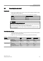


Table 6-4
Tightening torque of screws with ground terminals
Bolt
Screw-in depth
Tightening torque
M6
> 9 mm
8 Nm
M8
> 12 mm
20 Nm
M10
> 15 mm
40 Nm
Equipotential bonding
Terminals are provided on the bearing shield for the connection of an equipotential bonding
conductor.
6.7
Internal equipotential bonding
The equipotential bonding between the protective conductor terminal in the terminal box and
the motor housing is established through the terminal box fixing screws. These screws are
rated and designed as an "equivalent conductive connection" in relation to the protective
conductor cross-section specified for the phase conductor in standard (IEC / EN 60034-1).
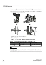
Equipotential bonding
In order to guarantee the current carrying capacity of the connection via the retaining bolts in
the event of a short circuit, make sure that the following conditions are fulfilled:
● Use only original gaskets.
● The contact points underneath the bolt heads or spring lock washers must be bare metal
and protected against corrosion.
● The standard cover fixing screws are an adequate equipotential bonding connection
between the terminal box cover and terminal box housing.
WARNING
Electric shock
If the equipotential bonding connection fails, parts of the machine may become live. If you
touch them, you will receive an electric shock. This could result in death, serious injury or
material damage.
When performing any installation work you must always take care to ensure that all
equipotential bonding connections remain effective.
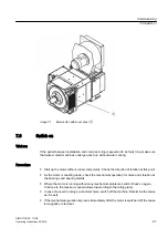
6.8
Connecting the auxiliary circuits
Auxiliary circuit
Terminal strips for cable cross-sections of up to 2.5 mm
2
are provided for connecting auxiliary
circuits, e.g. temperature sensor or anti-condensation heating.
Electrical connection
6.8 Connecting the auxiliary circuits
SIMOTICS DC 1GG6
58
Operating Instructions 02/2016
Содержание SIMOTICS DC 1GG6
Страница 2: ...08 02 2016 10 27 V4 00 ...
Страница 12: ...Table of contents SIMOTICS DC 1GG6 12 Operating Instructions 02 2016 ...
Страница 14: ...Introduction 1 1 About these instructions SIMOTICS DC 1GG6 14 Operating Instructions 02 2016 ...
Страница 62: ...Electrical connection 6 11 Completing connection work SIMOTICS DC 1GG6 62 Operating Instructions 02 2016 ...
Страница 70: ...Commissioning 7 8 Switch off SIMOTICS DC 1GG6 70 Operating Instructions 02 2016 ...
Страница 82: ...Operation 8 9 Faults SIMOTICS DC 1GG6 82 Operating Instructions 02 2016 ...
Страница 104: ...Maintenance 9 2 Repair SIMOTICS DC 1GG6 104 Operating Instructions 02 2016 ...
Страница 138: ...Service and Support SIMOTICS DC 1GG6 138 Operating Instructions 02 2016 ...
Страница 142: ...Quality documents SIMOTICS DC 1GG6 142 Operating Instructions 02 2016 ...
Страница 148: ...Checklists D 4 Inspection when the motor is running SIMOTICS DC 1GG6 148 Operating Instructions 02 2016 ...
Страница 152: ...W Wall face 39 Wall mounting 39 Water drain holes 45 Index SIMOTICS DC 1GG6 152 Operating Instructions 02 2016 ...
Страница 153: ......
Страница 154: ...Siemens AG Process Industries and Drives Postfach 48 48 90026 NÜRNBERG GERMANY www siemens com drives ...


