background image

Configuring the Mobile Panel 


Mobile Panels 2nd Generation 

166


Operating Instructions, 09/2018, A5E33876626-AC 


Note 
Observe the configuration sequence 
Configure the communication connection between the Mobile Panel and controller before 

creating the safety program. 
You must implement the following function blocks in your safety program: 


An FB198 for each Mobile Panel: F_FB_KTP_Mobile 


An FB199 for each connection box: F_FB_KTP_RNG 


FB215: ESTOP1; use this block to ensure that the operator must provide 

acknowledgment after an emergency stop before restarting the plant. You can find this 

block in the following block container of the "Safety Advanced" F-library: 

"Communication > Fail-safe HMI Mobile Panels > -- KTP Mobile --" 


Topology for connection box standard and connection box advanced 


NOTICE 
Parameterizing the internal switch 
If you are using an HMI device image from the scope of delivery of the  

WinCC (TIA Portal) V13 SP1 Update 4 software on your HMI device, the following applies: 
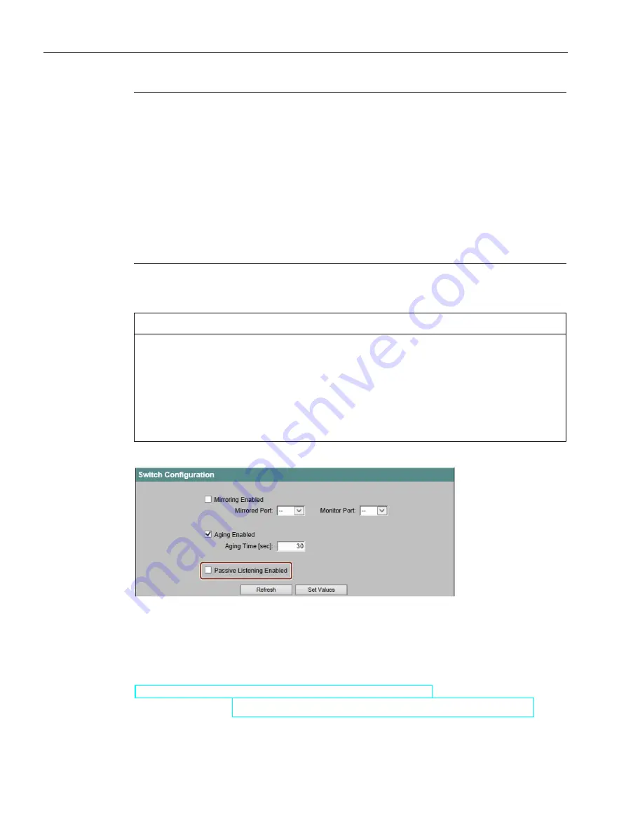
Parameterization of the internal switch of the connection box is necessary when one or 

more connection boxes are used in a line topology. The internal switch is parameterized via 

the Web server interface. During parameterization of the internal switch, disable the option 

"Passive Listening" to ensure interruption-free communication; see the following figure. 


You can find additional information on configuration in the information system of the 

TIA Portal. 

See also 

"SIMATIC Safety - Configuring and Programming" programming and operating manual 

(

http://support.automation.siemens.com/WW/view/en/54110126

) 

Application example (

https://support.industry.siemens.com/cs/ww/en/view/103497649

) 

Содержание SIMATIC HMI KTP700 Basic

Страница 1: ...____ ___________________ SIMATIC HMI HMI devices Mobile Panels 2nd Generation Operating Instructions 09 2018 A5E33876626 AC Preface Overview 1 Safety instructions 2 Installing system components 3 Handling the Mobile Panel 4 Parameterizing the Mobile Panel 5 Configuring the Mobile Panel 6 Commissioning a project 7 Operating a project 8 Fail safe operation 9 Maintenance and care 10 Technical specifi...

Страница 2: ...ly by personnel qualified for the specific task in accordance with the relevant documentation in particular its warning notices and safety instructions Qualified personnel are those who based on their training and experience are capable of identifying risks and avoiding potential hazards when working with these products systems Proper use of Siemens products Note the following WARNING Siemens prod...

Страница 3: ...ed to understand the operating instructions Knowledge of personal computers and the Microsoft operating systems is required to understand this manual Scope of the document The operating instructions apply to the following Mobile Panels 2nd Generation in combination with the corresponding connection boxes SIMATIC HMI KTP400F Mobile article number 6AV2125 2DB23 0AX0 SIMATIC HMI KTP700 Mobile article...

Страница 4: ...e HMI device Make sure that every supplement to the documentation that you receive is stored together with the operating instructions Style conventions Style Convention Scope Add screen Terminology that appears in the user interface for example dialog names tabs buttons menu commands Necessary entries for example limit tag value Path information File Edit Operational sequences e g menu command sho...

Страница 5: ...afe Mobile Panel KTP400F Mobile KTP700F Mobile KTP900F Mobile Safety related operator control Emergency stop stop button Enabling button Storage medium SD memory card USB flash drive WinCC WinCC Comfort V13 SP1 or higher WinCC Advanced V13 SP1 or higher STEP 7 STEP 7 V13 SP1 or higher Safety optional package STEP 7 Safety Advanced V13 SP1 or later optional package Information on standards You can ...

Страница 6: ... The figures can deviate from the particularities of the delivered device Picture components are marked with black position numbers on a white background etc Steps in the figures are identified with white process numbers on a black background according to the sequence in which they have to be executed See also Terms for fail safe operation Page 24 ...

Страница 7: ...obile Panel and connection box compatibility 29 2 Safety instructions 31 2 1 General safety instructions 31 2 2 Security management for HMI devices 36 2 3 Data protection 36 2 4 Notes about usage 37 2 5 Risk assessment of the plant 38 2 6 Important information on emergency stop stop button 39 2 7 Important notes for the enabling mechanism 40 3 Installing system components 43 3 1 Checking the deliv...

Страница 8: ... connection box 64 3 6 5 Connecting cables for a hardwired F system 66 3 6 6 Connecting Ethernet to the connection box 67 3 6 7 Setting the box ID of the connection box 70 3 6 8 Secure cables and seal screw glands 72 3 7 Connecting the KTP Mobile connecting cable to the connection box 73 3 8 Selecting the connection box 75 4 Handling the Mobile Panel 77 4 1 Holding the Mobile Panel and attaching i...

Страница 9: ...5 8 9 Displaying general system properties 117 5 8 10 Displaying information about the Mobile Panel 118 5 8 11 Display firmware 118 5 9 Changing Internet settings 119 5 9 1 Changing general settings 119 5 9 2 Setting the proxy server 120 5 9 3 Changing Internet security settings 121 5 9 4 Activating encryption protocols 123 5 9 5 Importing displaying and deleting certificates 124 5 10 Enabling PRO...

Страница 10: ...rolling and evaluating operator controls and display elements 184 6 5 1 Overview 184 6 5 2 Evaluating operator controls as direct keys 184 6 5 3 Controlling the LEDs of the function keys by means of system functions 187 6 5 4 Controlling and evaluating the illuminated pushbutton by means of system functions 187 6 5 5 Evaluating the key operated switch by means of system functions 188 7 Commissioni...

Страница 11: ... parts and repairs 218 10 6 Recycling and disposal 218 11 Technical specifications 219 11 1 Software license agreements 219 11 2 Certificates and approvals 219 11 3 Standards on operating safety 221 11 4 Electromagnetic compatibility 221 11 5 Mechanical ambient conditions 223 11 5 1 Storage conditions 223 11 5 2 Operating Conditions 223 11 6 Climatic ambient conditions 224 11 6 1 Long term storage...

Страница 12: ...11 10 3 Plug in terminal strip X10 245 11 10 4 Wiring of safety related operator controls 246 11 11 Interfaces of the connection box standard and connection box advanced 248 11 11 1 Position of the interfaces 248 11 11 2 Fast connector X1 and X2 249 11 11 3 Plug in terminal strip X10 249 11 11 4 Wiring of safety related operator controls 250 11 12 Communication with controllers 253 11 13 Scope of ...

Страница 13: ...used With a fail safe Mobile Panel you run the plant in fail safe mode You meet the requirements of Safety Integrity Level 3 and Performance Level PL e with a fail safe Mobile Panel An emergency stop stop switch and an enabling button are integrated in a fail safe Mobile Panel 2nd Generation You can hardwire the safety related operator controls or evaluate them in a PROFIsafe based F system with a...

Страница 14: ...ent of the Totally Integrated Automation Portal engineering framework 1 2 Design of the Mobile Panels The Mobile Panels 2nd Generation are available in the following device versions SIMATIC HMI Number of function keys Illuminated pushbutton Emergency stop stop button acknowledgment button Keyswitch KTP400F Mobile 4 2 Yes No KTP700 Mobile 8 2 No No KTP700F Mobile 8 2 Yes Yes KTP900 Mobile 10 2 No N...

Страница 15: ...fail safe Mobile Panel Drop protection for emergency stop stop switch for fail safe Mobile Panel Cover of the USB port Handle Function key blocks Display with touch screen Illuminated pushbutton The position of the emergency stop stop button makes it easily accessible Due to its profiled design the emergency stop stop button is easily accessible Two bumpers protect the emergency stop stop button a...

Страница 16: ...f the design of the fail safe HMI device KTP900F Mobile The other HMI devices of the type KTP Mobile are constructed similarly USB port with cover Threaded sleeve for mounting screw of the cable retainer not for KTP400F Mobile Handle Slot for an SD memory card not for KTP400F Mobile Nameplate 12 pin connector for the connecting cable Terminal compartment RJ45 socket PROFINET LAN ...

Страница 17: ...n and enabling button Transmission of the box ID RJ45 connector Plug connector 12 pin Retainer not required for KTP400F Mobile Label with order number length specification and product version Seal Terminal compartment cover Connector for the connection box The KTP Mobile connecting cable is available in the following lengths Product name and length Article number KTP Mobile 2 m connecting cable 6A...

Страница 18: ...03 0AX0 Connection box standard article number 6AV2125 2AE13 0AX0 Connection box advanced article number 6AV2125 2AE23 0AX0 Connection box compact The figure below shows the connection box compact Positioning mark There is also a red positioning mark on the connecting cable Align this mark with the positioning mark on the connection box when connecting Connection socket for the connecting cable Co...

Страница 19: ...s for the data cables Positioning mark There is also a red positioning mark on the connecting cable Align this mark with the positioning mark on the connection box when connecting Connection socket for the connecting cable Screw glands for power supply cables and F signal cables Cover of the connection socket Safety strap There are three LEDs on the front of the connection box that indicate the st...

Страница 20: ...or operating a Mobile Panel 2nd Generation Mobile Panel 2nd Generation 1 Mobile Panel or fail safe Mobile Panel 1 DVD with documentation and product information 1 Mobile Panels 2nd Generation Quick Install Guide The scope of delivery may contain additional documents Connection box compact 1 Connection box compact 1 DVD with documentation and product information 1 Accessory kit with mounting clips ...

Страница 21: ...owing accessories for the HMI devices of type KTP Mobile for example KTP Mobile wall mounting bracket KTP Mobile spare key Memory card Protective film 1 6 1 KTP Mobile wall mounting bracket The wall mounting bracket holds the Mobile Panel securely in place during stationary operation Hooks for the handle on the Mobile Panel Screw flange Safety bar for the Mobile Panel Holding bracket for the conne...

Страница 22: ...tched and dirty during operation One set of protective film contains 10 protective films Protective film 4 touch devices type 13 Protective film 7 touch devices type 13 Protective film 9 touch devices type 13 1 6 4 Storage media You can use the storage media to back up Mobile Panel data and copy data to the Mobile Panel Use the following storage media SIMATIC HMI Memory Card Siemens AG has approve...

Страница 23: ...lays on the Internet http www siemens com product 3SK Note Evaluation of the safety related operator controls via F DI modules Instead of a SIRIUS safety relay F DI modules can be used for the evaluation The F DI modules used must be appropriate for the required safety integrity level SIL performance level and category Depending on the safety integrity level SIL performance level and category requ...

Страница 24: ...one of the following software products to configure the KTP400F Mobile WinCC Comfort V13 SP1 Update 6 or higher WinCC Advanced V13 SP1 Update 6 or higher You also need the HSP0168 HMI KTP400F Mobile V1 0 or higher To operate a KTP400F Mobile in a PROFIsafe based F system you need the optional package STEP 7 Safety Advanced V13 SP1 or higher See also Configuring a fail safe Mobile Panel Page 170 1 ...

Страница 25: ...safe automation systems up to SIL3 PROFIsafe implements safety related communication with a special user data format and a special protocol PROFIsafe is specified for PROFINET in the standard IEC 61784 3 Safe operating state If an unexpected event occurs during plant operation that poses a risk to persons or equipment the plant must respond with a defined safety shutdown Protection of personnel ag...

Страница 26: ...d operator controls communication with the F system is performed via PROFIsafe When configuring the safety functions with the STEP 7 Safety Advanced optional package fail safe operation according to SIL 3 or Performance Level e and Category 4 is possible with an HMI device of the type KTPx00F Mobile The safety related operator controls can be configured as fail safe inputs in the safety program Em...

Страница 27: ...p button is called the emergency stop button E stop button evaluated by PROFIsafe This operating mode is intended for a PROFIsafe based F system If you press the emergency stop stop button an emergency stop is triggered in the plant The emergency stop stop button lights up when active that is if the HMI device has been registered in the safety program In this operating mode the emergency stop stop...

Страница 28: ...f you disconnect the fail safe Mobile Panel without logging off the connection box a PROFIsafe communication error occurs and the plant goes into safe operating mode according to the configured shutdown behavior Connection point recognition The connection point recognition is a function that you can configure for connection boxes Once you have configured connection point recognition you can determ...

Страница 29: ...ion addresses the following compatibility Ccompatibility of Mobile Panels 2nd Generation to connection box PN Basic and PN Plus Ccompatibility of Mobile Panels 1st Generation to connection boxes compact standard und advanced The Mobile Panels 2nd Generation are not compatible with the connection box DP Basic and connection box DP Plus Ccompatibility of Mobile Panels 2nd Generation connection box P...

Страница 30: ... 0BB01 0AX0 6AV6645 0BC01 0AX0 Mobile Panel 277 8 Article numbers 6AV6645 0CA01 0AX0 6AV6645 0CB01 0AX0 6AV6645 0CC01 0AX0 Mobile Panel 277 10 Article number 6AV6645 0BE02 0AX0 Restrictions Only one hardwired system F system with a stop function and enabling function is permitted with a Mobile Panel 1st Generation PROFIsafe communication is not possible with predecessor devices therefore a PROFIsa...

Страница 31: ...llow closely the safety regulations and procedural instructions in each situation Observe the safety and accident prevention regulations applicable to your application in addition to the safety instructions given in this document Safety during configuration and operational safety of the plant WARNING Personal injury or material damage due to improper configuration of the plant The configuration en...

Страница 32: ...devices simultaneously can cause material damage Prevent simultaneous operation of the plant from multiple devices by configuring the assignment of operating rights to only one HMI device Parameter assignment fail safe Mobile Panels WARNING Personal injury or material damage with different operating modes in a plant area If you assign different operating modes to the connection boxes in a contiguo...

Страница 33: ...ements for operational safety on the part of the operator Vendors are also required to comply with certain measures for monitoring the product We therefore provide a special newsletter about product development and properties to inform you about important safety aspects for the operation of plants To ensure that you are always kept up to date in this regard and can make changes to your plant you s...

Страница 34: ...tarting with the last and finishing with the first Label the electrical system in accordance with the applicable safety provisions when work is to be carried out Always adhere to the safety provisions applicable in the country of use Strong high frequency radiation NOTICE Observe immunity to RF radiation The device has an increased immunity to RF radiation according to the specifications on electr...

Страница 35: ...wn of the plant Note The function of the emergency stop stop button must be checked regularly See Testing Mobile Panel readiness for operation Page 85 Industrial Security Siemens provides products and solutions with industrial security functions that support the secure operation of plants systems machines and networks In order to protect plants systems machines and networks against cyber threats i...

Страница 36: ...utomation software en software update service Notes on protecting administrator accounts A user with administrator privileges has extensive access and manipulation options in the system Therefore ensure there are adequate safeguards for protecting the administrator accounts to prevent unauthorized changes To do this use secure passwords and a standard user account for normal operation Other measur...

Страница 37: ...nment inside the building Additional information is available in the section Operating Conditions Page 224 Industrial applications The HMI device is designed for industrial applications It conforms to the following standards Requirements for emitted interference EN 61000 6 4 A1 Requirements for interference immunity EN 61000 6 2 Use in mixed use zone Under certain circumstances you can use the HMI...

Страница 38: ...isk assessment and risk reduction ISO 13849 1 Safety of machinery Safety related parts of control systems General principles for design The results of the risk assessment leads to the Performance Levels a to e in accordance with ISO 13849 1 which indicates how the safety related system components must be designed if the stop or emergency stop functions are needed locally in a plant segment or glob...

Страница 39: ...ction 9 2 5 3 The stop function is not to be used as a replacement for safety equipment Hardwired F system The emergency stop stop button can trigger a safe machine stop or be looped into the safety circuit of the F system based on the configuration of the F system The signals of the emergency stop stop button are wired differently in the connection boxes For connection box compact and connection ...

Страница 40: ... mechanism The enabling mechanism consists of the enabling button installed on the HMI device and the corresponding logic in the HMI device The operating modes relevant for the enabling mechanism are Setup mode In setup mode safety has to be ensured in a different way than in automatic mode During setup mode personnel enter danger zones of the plant in which controlled movements must be possible M...

Страница 41: ... hazardous operating state requires a second specific operation with another key on the HMI device Consider this during configuration NOTICE Enabling button must not be fixed Fixing the enabling button in one of its positions can cause malfunctions in the fail safe automation system Make sure that the enabling button is not being held permanently in any of its positions Note The enabling button is...

Страница 42: ...tion on discrepancy errors The enabling button has two channels Both channels must be activated at the same time for the enable and panic switch positions If only one channel is activated a discrepancy error occurs and enabling is no longer possible To reactivate enabling press the enabling button once completely into the panic position and then release it ...

Страница 43: ...ng the connection box compact 3 2 1 Mounting position mounting cutout and clearance Mounting position The connection box is designed for installation in the following types of fixed enclosure Mounting cabinets Control cabinets Control panels Consoles The connection box compact can be installed in any mounting position Mounting cutout The degree of protection is guaranteed if the following conditio...

Страница 44: ...et and be able to connect the connecting cable without any problems you need the clearance indicated in the figures below all dimensions in mm Note that in addition to the mounting depth of the connection box a rear clearance is re quired based on the leads and plugs used Note Ensure that the maximum ambient temperature as detailed in Operating Conditions Page 224 is not exceeded when installing t...

Страница 45: ...ox with a damaged mounting seal 2 Insert the connection box in the mounting cutout Secure the connection box to prevent it from falling out 3 Place one mounting clip into each of the four cutouts marked 4 Fasten the mounting clips The permitted torque is 0 2 Nm You can find information on the electrical connection of the connection box in the section Connecting the connection box Page 59 3 3 Insta...

Страница 46: ...mounting of the Anschuss box standard and the connection box advanced on a flat metal surface such as a control cabinet wall Requirement 4 M5 cylinder head screws 1 suitable screwdriver Procedure In this example the fastening described is outside of a control cabinet wall 1 Hold the connection box on the area where you want to mount it 2 Mark locations for the mounting holes 3 Drill holes or threa...

Страница 47: ...t 1 torque screwdriver with T10 insert Procedure 1 Position the safety bar as shown in the figure Note the type of your HMI device in doing so The figure for example shows the position of the safety bar for a KTP900 KTP900F Mobile 2 Fasten the safety bar screws with the T10 screwdriver in the required places The permitted torque is 0 8 Nm 3 Slide the holding bracket for the connecting cable from o...

Страница 48: ...terial damage Select a mounting location with sufficient load carrying capacity for the total weight of the wall mounting bracket HMI device and connecting cable Choose the corresponding fixing material Weight information is available in section Technical specifications Page 233 NOTICE Do not attach the wall mounting bracket to a moving or vibrating enclosure When attaching the wall mounting brack...

Страница 49: ...erating Instructions 09 2018 A5E33876626 AC 49 Clearance Consider the space required for the connecting cable used and the height that the HMI device extends up and over the wall mounting bracket The figure below shows the minimum clearance required around the wall bracket Space requirements for connecting cable ...

Страница 50: ...mounting bracket to a control cabinet A level bolting surface 3 M5 bolts and a suitable screwdriver 3 M5 nuts and a suitable wrench Procedure 1 Place the wall mounting bracket level on the mounting surface 2 Mark the drill holes at the indicated locations in the figure on the right 3 Drill 3 holes for M5 type bolts based on your mounting requirements 4 Fasten the wall mounting bracket with the bol...

Страница 51: ...and damage the HMI device accordingly Pay attention to cleanliness Keep foreign objects and liquids away while working on the terminal compartment of the HMI device Connection sequence Keep to the following connection sequence SD memory card if required KTP Mobile connecting cable Connection box Configuration PC if required 3 5 2 Inserting the SD memory card All Mobile Panels 2nd Generation with t...

Страница 52: ...Mobile Panel insert or remove the SD memory card with an appropriate tool made of plastic Requirement The Mobile Panel is deenergized The terminal compartment is open The connection cable is not attached You have taken precautions to protect your device see section Connection information Page 51 A suitable tool made of plastic Procedure 1 Turn the storage medium so that the contacts are pointing t...

Страница 53: ...e 51 One torque screwdriver with cross tip insert size 2 Procedure 1 Plug the connector into port X80 Note the mechanical coding on the connector 2 Plug in the RJ45 connector at port X1 Make sure that the connector audibly engages 3 Place the terminal compartment cover over the terminal compartment Tighten the corresponding screws using a torque of 0 2 Nm Note When closing the terminal compartment...

Страница 54: ...Project HMI device image Additional project data Procedure 1 Connect the configuration PC to an Ethernet network 2 Connect the Mobile Panel to a connection box which is connected to the configuration PC via the Ethernet network The figure below shows an example of how to connect a KTP900F Mobile to a connection box compact Section Transferring a project with WinCC Page 191 describes how to transfe...

Страница 55: ... see section Connection information Page 51 One torque screwdriver with cross tip insert size 2 Procedure Open 1 Place the HMI device on its front Screws for terminal compartment cover Retainer not for KTP400F Mobile Screw for the retainer not with KTP400F Mobile Connecting cable 2 All Mobile Panels 2nd Generation with the exception of the KTP400F Mobile Loosen the screw 3 Loosen the screws of the...

Страница 56: ...nical coding on the connector 7 Plug in the RJ45 connector at port X1 Make sure that the connector audibly engages 8 Place the terminal compartment cover over the terminal compartment Tighten the corresponding screws using a torque of 0 2 Nm Note When closing the terminal compartment cover make sure that the corresponding seal is undamaged and properly seated Otherwise the specified degrees of pro...

Страница 57: ...ble is removed You have taken precautions to protect your device see section Connection information Page 51 A suitable tool made of plastic for gripping the SD memory card One torque screwdriver with cross tip insert size 2 Procedure Removing the SD memory card 1 Grab the SD memory card with an appropriate tool 2 Pull the SD memory card from the slot to the center of the terminal compartment Inser...

Страница 58: ...ash drive for commissioning and maintenance purposes Degrees of protection not guaranteed with USB flash drive When a USB flash drive is connected to the USB port the degrees of protection specified for the Mobile Panel are not guaranteed Do not connect a USB device if dust or moisture is present at the location of use that can enter the HMI device Requirement An industrial grade USB flash drive P...

Страница 59: ...ly Pay attention to cleanliness Keep foreign objects and liquids away while working on the connection box Take care when working on the connection box that conducting materials such as bare cable leads do not come into contact with the electrical circuits NOTICE Observe local installation regulations Observe the local installation regulations and the local installation conditions such as protectiv...

Страница 60: ...ion box advanced The connection boxes standard and advanced must be opened for connecting and setting the box ID To avoid damage to the connection box read the information in the section General safety instructions Page 31 about working in and on electrical systems and about ESD Requirement The connection box is de energized Torque screwdriver with T10 insert Procedure Open Cover Screws Screw glan...

Страница 61: ...Close Follow the steps for opening in reverse order NOTICE Permissible torque The connection box enclosure is made of plastic Therefore the mounting hole threads cannot handle the same amount of stress as a comparable metallic enclosure If the screws are tightened with too great a torque or more than 20 times there is risk of damage to the thread Do not exceed 0 4 to 0 5 Nm of torque when tighteni...

Страница 62: ...ed by means of shielded data cables and their shielding is connected at both ends to the grounding protective conductor the impedance of the additionally installed equipotential bonding conductor must not exceed 10 of the shielding impedance The cross section of a selected equipotential bonding conductor must be capable of handling the maximum equalizing current Equipotential bonding cables are re...

Страница 63: ...al bonding of the connection boxes to the equipotential busbars Ground connection Equipotential bonding conductor cross section 1 5 mm2 Equipotential busbar for equipotential bonding cables grounding connection and shield support of the data cables Ethernet cable Equipotential bonding conductor cross section 16 mm2 Parallel routing of the equipotential bonding conductor and data cable Cable clip C...

Страница 64: ...m of 36 V DC and also does not exceed m 36 V DC in case of fault Refer to the information in the data sheet for overvoltage protection in the event of an internal error or take appropriate voltage limiting measures such as the use of a surge protection device NOTICE External protective circuit An external protective circuit is required for operation with 24 V DC please refer to section 7 Lightning...

Страница 65: ...nnection box and the cable glands for cable entry Connection for functional ground M24 P24 Screw gland 4 Connect the equipotential bonding conductor to the equipotential busbar 5 Connect the equipotential bonding conductor to the terminal for the functional ground of the connection box Connect the equipotential bonding conductor of the connection box as described in the section Equipotential bondi...

Страница 66: ...ength of 30 m for cables between the connection box and the evaluation unit Note If a connection box is to be operated in E stop button evaluated by PROFIsafe mode the connection box cannot be wired according to a hardwired F system Requirement The connection box standard or advanced is open Read the information on the number of connecting cables required in the section Specification of cables to ...

Страница 67: ... box standard and connection box advanced Page 249 Connection box compact Page 245 5 For connection box standard and connection box advanced When all the required work has been completed in the connection box close it 3 6 6 Connecting Ethernet to the connection box You can connect a controller or other Ethernet devices to the connection box Compatible controllers are listed in the section Communic...

Страница 68: ...ection box Connection box compact Connection box standard Connection box advanced 25 m Between Mobile Panel and PROFINET PROFIsafe station Connection box compact 100 m Connection box standard Connection box advanced 125 m Requirement The connection box is mounted Connection box compact 1 preassembled Ethernet cable including Ethernet connector Recommendation Use an angled connector for example an ...

Страница 69: ...ernet cable with the RJ45 socket marked in the figure below Note LEDs on the RJ45 socket not active The two LEDs at the RJ45 socket of the connection box compact are not supported by the hardware and do not light up during operation Connection boxes standard and advanced 1 Strip the insulation on the Ethernet cable as shown in the figure below 2 Open fast connector 1 Fast connector 1 Fast connecto...

Страница 70: ...etting the box ID of the connection box You need to set a box ID for each connection box If configured the box ID can be read by the HMI device and transmitted to the PLC The box ID allows connection point detection The procedure is described in the section Configuring connection point detection Page 179 Note You need to set a box ID for each connection box Do not assign the same box ID twice Note...

Страница 71: ...r connection box standard and connection box advanced The connection box is open The connection box is disconnected from its power supply A suitable tool made of plastic Procedure 1 Rotate the arrows of the rotary coding switch to the required hexadecimal value using a suitable tool Values from 00 to FF 0 to 255 in decimal form can be set with the rotary coding switches When setting the box ID Use...

Страница 72: ...ary encoding switch for less significant bits 2 For connection box standard and connection box advanced When all the required work has been completed in the connection box close it See also Assigning a safety related operating mode Page 142 3 6 8 Secure cables and seal screw glands Once all cables are connected to the connection box the following final steps should be carried out Connection box co...

Страница 73: ... advanced 1 Check whether the cover is located in the cable glands that are not in use 2 If a cover is missing replace it 3 Tighten the screw cap This will ensure IP65 degree of protection for the connection box standard or the connection box advanced 3 7 Connecting the KTP Mobile connecting cable to the connection box The connecting cable can be connected to the connection box using the connector...

Страница 74: ...on socket of the connection box Additional characteristics of the Mobile Panel are described in the section Testing Mobile Panel readiness for operation Page 85 Unplugging NOTICE PROFIsafe based F system Logoff required In a PROFIsafe based F system logoff from the safety program is required before unplugging the connecting cable If you unplug the connecting cable without logoff the plant will swi...

Страница 75: ...ecting cable or the cover of the connection socket is inserted 3 8 Selecting the connection box The connection box is generally removed in the reverse order used for installing and connecting Requirements No Mobile Panel is connected to the connection box The cover of the connection socket for the connecting cable is located on the connection box Procedure Connection box compact 1 Switch off power...

Страница 76: ... cables at the port X10 The Ethernet cables at Fast Connector X1 and Fast Connector X2 4 Thread all connecting cables through the associated cable glands out of the connection box 5 Close the connection box 6 Close off all cable glands with a cover 7 Remove the four outermost screws used to fasten the connection box 8 Remove the connection box from its mounting location See also Connecting the KTP...

Страница 77: ...ree hand you can operate all operator controls on the front of the device and the emergency stop stop button You can activate the enabling button with the hand holding the HMI device The enabling button is optimally accessible NOTICE Holding the HMI device during setup mode Potentially dangerous movements can be controlled manually if setup mode is activated To ensure that the emergency stop stop ...

Страница 78: ...tional measures as described in the section Organizational measures Page 28 NOTICE Operability of the emergency stop stop button Placing the HMI device into an unsuitable wall mounting bracket can impair the operability of the emergency stop stop button Only use the KTP Mobile wall mounting bracket Page 21 Note If the HMI device with the KTP Mobile connecting cable is not connected to the connecti...

Страница 79: ... system functions Page 188 Function keys The function keys can be used for fast digital input The function depends on the corresponding project The corresponding configuration is described in the section Function keys Page 204 The LED can light up to signal that the corresponding function has been triggered Illuminated pushbutton and can be used for high speed digital input The illuminated pushbut...

Страница 80: ...0 and II Meaning of the switch positions Switch position I and II The configured function for this switch position is executed Switch position 0 The called function is canceled Remove the key if you do not use the HMI device The key can only be removed in switch position 0 The key does not have HMI device specific coding You can use the key for any KTP Mobile type HMI device Spare keys may be orde...

Страница 81: ...nd sent to the connection box over the connecting cable For setup mode these signals must be wired dual channel from the connection box to the F system or configured via PROFIsafe Enabling button For a hardwired F system When a SIRIUS safety relay is used the enabling button meets the requirements of Safety Category 3 in accordance with EN ISO 13849 1 Requirement The HMI device is connected to a c...

Страница 82: ... Panic Opened The figure below shows the switching sequence for normal operation The figure below shows the switching sequence for panic operation 2 Release the enabling button If the enabling button is in switch position 3 the Enable setting is skipped when the button is released Note Releasing the enabling button and the Panic switch position do not require acknowledgement of the safety shutdown...

Страница 83: ... stop stop button lights up as soon as the emergency stop function becomes available An emergency stop or stop can only be triggered when the fail safe HMI device is attached to a connection box Emergency stop stop button For a hardwired F system When a SIRIUS safety relay is used the emergency stop stop button meets the requirements of Safety Category 3 in accordance with EN ISO 13849 1 When you ...

Страница 84: ...ease requirements If you have operated the emergency stop stop button and thereby shut down the fail safe automation system a situation entailing danger may still remain You are only allowed to release the emergency stop stop button under the following conditions The cause of the emergency stop stop has been eliminated A safe hot restart of the fail safe automation system is possible Turn the emer...

Страница 85: ... the connecting cable into the connection box If the HMI device does not start the wires at interface X10 in the connection box may have been crossed Check the connected wires and change the connections if necessary When plugging and unplugging the connecting cable follow Connecting the KTP Mobile connecting cable to the connection box Page 73 The HMI device display lights up once the cable is con...

Страница 86: ...yed The Transfer dialog is displayed A project is started Testing the enabling button and emergency stop stop button function Note Before testing the enabling button and emergency stop stop button functions read the information in the following sections Operating the enabling button Page 81 Pressing the emergency stop stop button Page 83 The HMI device must be connected to a connection box for the...

Страница 87: ...vice on the Internet https support industry siemens com cs ww en Enter the article number of your HMI device as a search term and filter the contributions according to the by contribution type Download 5 2 Desktop and Start Center Once the HMI device has been started the display shows the desktop Desktop Start Center Start menu Icon for screen keyboard The Start Center The Start Center buttons hav...

Страница 88: ...ols shown in the dialogs are touch sensitive Touch objects are operated in the same way as mechanical keys You activate an operator control by pressing it with your finger To double click touch an operator control twice in succession 5 4 Installed programs Installed programs The following programs are installed on the HMI device Installed programs Icon File formats PDF Viewer PDF Internet Explorer...

Страница 89: ...rd is not entered only the Transfer and Start buttons can be operated NOTICE Keeping the password If the password is no longer available you have no access to the Control Panel and the Windows CE taskbar Backup password to protect it against loss 5 5 2 Using the HMI device in password protected security mode If security mode has been activated only the Transfer and Start buttons can be operated wi...

Страница 90: ...skbar button in the Start Center The following dialog appears 2 Enter the required password 3 Confirm your entry with OK The dialog will close and the selected operator control open 5 6 Control Panel 5 6 1 Opening the settings The Control Panel can be opened as follows With the Settings button in the Start Center In the Windows CE start menu with Settings Control Panel The figure below shows the o...

Страница 91: ...Activating encryption protocols Page 123 Setting the character repeat rate of the screen keyboard Page 98 Setting the double click Page 99 Specifying the IP address and name server Page 132 Specifying the logon data Page 133 Backing up registry information and temporary data Page 115 Displaying information about the Mobile Panel Page 118 Restarting the HMI device Page 101 Display firmware Page 118...

Страница 92: ...ion connections Page 159 Displaying general system properties Page 117 Displaying the memory distribution Page 111 Specifying the computer name of the HMI device Page 131 Parameterizing Transfer Page 109 Setting the project storage location and start delay Page 111 Configuring e mail Page 134 Configuring Telnet for remote control Page 136 Configure Sm rt Server Page 136 Configure Web Server Page 1...

Страница 93: ... applied with the button To cancel the entry press the button The dialog closes 6 To close the Control Panel use the button The Start Center is displayed See also Configuring the screen keyboard Page 97 5 6 4 Display types for the screen keyboard The screen keyboard is used for entering alphanumeric numeric and special characters As soon as you touch a text box a numeric or alphanumeric screen key...

Страница 94: ...yboard is only displayed when followed by a space If the character is followed by a letter then the result will be an accent such as á Shift level The shift level has uppercase letters and other special characters The alphanumeric keyboard is always displayed after a restart Numerical screen keyboard By pressing the Num button you can switch between the numerical and alphanumerical screen keyboard...

Страница 95: ...itching from full display to reduced display Switching from reduced display to full display Closing of reduced display of the screen keyboard Brief touch Hide screen keyboard Long touch and move at the same time Move the screen keyboard Scaling the screen keyboard Only available for devices as of a display size of 7 and when the Show Resize button option is activated see section Configuring the sc...

Страница 96: ...acklighting decreases with increasing service life To avoid shortening the service life of the backlighting unnecessarily set a reduction of the backlighting Requirement The Control Panel is open Procedure 1 Open the Display Properties dialog using the Display icon Slider Reduce brightness Increase brightness Indicates the set value 2 To increase the brightness press The brightness changes by 5 ea...

Страница 97: ...le screen keyboard activate the check box Show Resize Button If Show Resize Button is activated the Resize button is displayed in the open screen keyboard This function is not available for 4 HMI devices 3 If you want to check the settings open the screen keyboard with the Open Input Panel button Set the required size and position of the screen keyboard using the following buttons of the screen ke...

Страница 98: ...n select the Enable character repeat check box 3 To change the delay press a button or the slider in the Repeat delay group Moving the slider to the right reduces the delay Moving it to the left extends the delay time 4 To change the repeat rate press a button or the slider in the Repeat rate group Moving the slider to the right speeds up the repeat rate Moving to the left will slow down the repea...

Страница 99: ...creen Interval between the two clicks of a double click Requirement The Control Panel is open Procedure 1 Open the Mouse Properties dialog using the Mouse icon Checkered pattern icon Test icon 2 Double click the Checkered pattern icon After the double click the colors in the pattern are inverted White boxes become gray The timeframe for the double click is saved 3 Check the double click Press the ...

Страница 100: ...arallax may occur on the touch screen depending on the mounting position and perspective To prevent any resulting operating errors you may need to calibrate the touch screen Requirements A touch pen The Control Panel is open Procedure 1 Open the OP Properties dialog using the OP icon 2 Change to the Touch tab 3 Press the Recalibrate button The following dialog is displayed ...

Страница 101: ...etained 6 Close the OP Properties dialog with OK The touch screen of the HMI device is calibrated 5 7 6 Restarting the HMI device You need to perform a restart in the following situations You have enabled or disabled the PROFINET IO direct keys see section Enabling NTP Page 127 You have changed the time zone and activated daylight saving time see section Setting the date and time Page 104 You have...

Страница 102: ...ties dialog using the OP icon 2 Change to the Device tab 3 Click the Reboot button The following dialog appears Button for restart Button for restoring factory settings and subsequent restart 4 Press one of the following buttons Reboot Restart the HMI device immediately Prepare for Reset Reset the HMI device to factory settings Note Press Prepare for Reset to delete the operating system and projec...

Страница 103: ...e project language is changed the country specific settings are also changed Requirement The Control Panel is open Procedure 1 Open the Regional and Language Settings dialog using the Regional Settings icon Region selection box 2 Select the required region in the selection box 3 Navigate to the Number Currency Time and Date tabs one after the other 4 Set the required regional settings in the selec...

Страница 104: ...the Time Zone selection box 3 Press the Apply button The time of day shown in the Current Time field is adjusted correspondingly to the selected time zone 4 Set the date in the selection box 5 Set the current time of day in the Current Time entry field 6 Press the Apply button The entry is applied Note The system does not automatically switch between standard time and daylight saving time 7 If you...

Страница 105: ...manual http support automation siemens com WW view en 54110126 NOTICE Synchronizing the date and time If the data and time is not synchronized and time based reactions are triggered by the HMI device malfunctions in the PLC may occur Synchronize the date and time if time based reactions are triggered in the PLC 5 8 3 Entering and deleting a password You can set and delete passwords with the follow...

Страница 106: ...e dialog and the screen keyboard close Security mode as described in the section Using the HMI device in password protected security mode Page 89 is active Canceling password protection 1 Double click on the Password icon The following dialog appears 2 Enter the password in the Password text box The following dialog appears 3 Delete the entry in the Password text box The entry in the Confirm passw...

Страница 107: ...n assigned to the button is not executed In addition the reduction of the backlighting according to the settings of the screen saver is canceled NOTICE Activating the screen saver Display content that is not changed for a long period can remain dimly visible in the background for a long time This effect is reversible when you use a screen saver with moving image Therefore activate the screen saver...

Страница 108: ...vating a screen saver If you enter a value outside the range of 25 to 90 a message will appear and the value is reset to 25 5 The Allow manual dim up at deactivation of screensaver for the Blank Screen screen saver works as follows If the option is activated you can dim the display brightness on deactivation of the screen saver The brightness is increased as long as you keep pressing the touch scr...

Страница 109: ...a transfer is in progress and want to confirm with OK an error message is displayed Procedure 1 Open the Transfer Settings dialog using the Transfer icon Transfer group Digital signatures group Transfer channel group Button for parameter assignment of the transfer channel properties 2 Change to the General tab 3 In the Transfer group select whether you want to enable or disable Transfer mode Selec...

Страница 110: ...an HMI device image select the Validate Signatures check box This function is available in connection with an HMI device image that is compatible with WinCC TIA Portal V14 or higher Image signatures are checked starting with V14 If you transfer an image that is compatible with a version before V14 an error message is displayed To transfer an unsigned image that is compatible with a version before ...

Страница 111: ...che memory available and used RAM available and used NOTICE Malfunction If you change the allocation of the memory malfunctions may occur Do not change the memory allocation in the Memory tab unless the message Insufficient memory is displayed Additional information is available in the information system of the TIA Portal 5 8 6 2 Setting the project storage location and start delay There are vario...

Страница 112: ...network During the next backup process the project s source file is stored in the specified location 4 Select the desired delay time for project start from the Wait sec selection box The delay time sets how long the Start Center is displayed before the project starts Permissible values are 1 3 5 and 10 seconds for HMI device image versions V14 SP1 additionally 60 seconds You can also select 0 seco...

Страница 113: ...ring tab 3 If you want to enable memory management select Shut down HMI Runtime 4 Confirm your entries with OK Result Memory management is activated An open project is closed under these circumstances Insufficient RAM RAM needs to be reorganized An alarm is then triggered on the HMI device Restart the project on the HMI device 5 8 6 4 Activate deactivate retentivity of the alarm buffer on the HMI ...

Страница 114: ... the retentivity When you deactivate the retentivity of the alarm buffer and still need the data in the alarm buffer back up this data before deactivating the retentivity in a log Changing the retentivity behavior using the configuration As of WinCC TIA Portal V15 1 you can also change the retentivity behavior with the Persistent alarm buffer function under Runtime settings Alarms General Default ...

Страница 115: ...torage medium is inserted 2 To back up the current registry entries press the Save Registry button The current registry entries will be backed up in the flash memory The HMI device loads the saved registry information the next time it boots 3 To back up temporary files press the Save Files button All files from the temporary memory will be backed up in the flash memory You can access the files sav...

Страница 116: ...rinter Selection list for the interface Network address of the printer Drop down list for printing paper format Orientation group with radio buttons for print orientation Print quality check box Check box for color quality valid only for Brother HL 2700 printer Color printing check box 2 Select a printer from the Printer Language selection list 3 Select the port for the printer from the Port selec...

Страница 117: ...t as specified 5 8 9 Displaying general system properties Use this function to display the general system information relating to the operating system processor and memory You will need this information when contacting Technical Support Requirement The Control Panel is open Procedure Open the System Properties dialog using the System icon The following figure shows an example Information on the ve...

Страница 118: ...he OP icon 2 Change to the Device tab HMI device name Version of the HMI device image Version of the bootloader Bootloader release date Size of the internal flash memory in which the HMI device image and project are stored MAC address 1 of the HMI device See Restarting the HMI device Page 101 Device specific information is displayed Note The size of the flash memory does not correspond to the avai...

Страница 119: ...module Firmware version of the connection box 5 9 Changing Internet settings 5 9 1 Changing general settings You can use this function to set the homepage and search engine page for an Internet connection over Internet Explorer Requirement The Control Panel is open Your system administrator has provided the necessary information for the setting Procedure 1 Open the Internet Options dialog using th...

Страница 120: ...e general parameters for the Internet browser have been set The settings take effect the next time you start the Internet browser 5 9 2 Setting the proxy server Use this function to configure the type of Internet access Requirement The Control Panel is open Your system administrator has provided the necessary information for the setting Procedure 1 Open the Internet Options dialog using the Intern...

Страница 121: ... proxy server should not be used Only the start of the addresses is required Separate the addresses with a semicolon Confirm your entries with OK or close the dialog with Cancel 8 To use a local address select the Bypass for local address check box 9 Confirm your entries The dialog closes The parameters for the LAN connection have been assigned 5 9 3 Changing Internet security settings A cookie ty...

Страница 122: ... Select Trusted Sites if you want to view and edit the set trusted websites 4 Select Sites The following dialog appears 5 To add the website displayed in the Add this web site field to the list of trusted sites select Add 6 To delete the website displayed in the Add this web site field from the list of trusted sites select Remove 7 If server verification is required for all websites on the list of...

Страница 123: ... or deactivate the usage of encryption protocols Read General safety instructions Page 31 Requirement The Control Panel is open Your system administrator has provided you with the necessary information Procedure 1 Open the Internet Options dialog using the Internet Options icon 2 Change to the Advanced tab Available encryption protocols Warning upon switch between secure and non secure data transm...

Страница 124: ...icate consists of structured data which confirms ownership and other properties of a public key Read General safety instructions Page 31 Requirement The Control Panel is open A USB stick with one or more valid certificates is prepared Your system administrator has provided you with the necessary information Procedure 1 Open the Certificates dialog using the Certificates icon List of trusted certif...

Страница 125: ... for importing certificates for the HMI device 6 Close the dialog with OK 7 In the subsequent file selection dialog select the desired certificate on the USB flash drive and confirm with OK The certificate will be imported and displayed in the list on the Stores tab 8 You can use the View button to display the properties of a certificate Name of the selected certificate Identity information and ot...

Страница 126: ...ncy stop stop button and enabling button over PROFIsafe Use of PROFINET direct keys Requirement The Control Panel is open Procedure 1 Open the Profinet dialog using the PROFINET icon Enables or disables the PROFINET IO direct keys Text box for the device name MAC address of the HMI device 2 Select the PROFINET IO enabled check box 3 Enter the PROFINET device name of the HMI device NOTICE Device na...

Страница 127: ...tc are not permitted The device name must not start or end with the character The device name must not take the form n n n n n 0 to 999 The device name must not start with the character string port xyz x y z 0 to 9 4 Confirm your entries The dialog closes 5 Restart the HMI device see section Restarting the HMI device Page 101 5 11 Enabling NTP To obtain the time of the HMI device from a time serve...

Страница 128: ...0 000 seconds 5 Press the Configure button The following dialog is displayed If you do not enter a time the message Second field wrong data type will appear Enter a time 6 Enter the DNS name of the time server under Name You can also enter the IP address of the time server 7 Use the Test button to check the accessibility of the time server The communication connection to the time server is establi...

Страница 129: ... than one device is assigned the same PROFIsafe address an emergency stop is triggered and the plant switches to the defined safe state Assign a PROFIsafe address to the HMI device that is unique within the corresponding local network segment Note PROFIsafe addresses must match For PROFIsafe communication to work the PROFIsafe address of the HMI device must match the PROFIsafe address in STEP 7 Th...

Страница 130: ...work offers the following options for example Exporting or importing of recipe data records on or from a server Storing alarm and data logs Transferring a project Printing via the local network Backing up data Addressing computers Computers are usually addressed using computer names within a PROFINET network These computer names are translated from a DNS or WINS server to TCP IP addresses This is ...

Страница 131: ...vice You can use this function to assign a computer name to the HMI device The computer name is used to identify the HMI device in the local network Requirement The Control Panel is open NOTICE Computer name must be unique Communication errors may occur in the local network if you assign a computer name more than once Enter a unique computer name in the Device name text box Procedure 1 Open the Sy...

Страница 132: ... Connections icon Your system administrator has provided the necessary information for the setting Procedure 1 Touch the PN_X1 icon The following dialog appears 2 If you need automatic address assignment select the Obtain an IP address option button 3 If you need manual address assignment select the Specify an IP address radio button NOTICE IP address must be unique An address conflict will occur ...

Страница 133: ...rol Panel is displayed The HMI device is addressed in the local network 5 13 4 Specifying the logon data Use this function to enter the information for logging onto local networks Requirement The Control Panel is open Your system administrator has provided you with the necessary information Procedure 1 Open the Network ID dialog using the Network ID icon 2 Enter your user name in the User name tex...

Страница 134: ... 2 Change to the Email tab Setting of the SMTP server Name of the sender and e mail account Advanced button for additional settings 3 Specify the SMTP server Select the Use the default of option if you want to use the SMTP server configured in the project Clear the Use the default of option if you do not want to use the SMTP server configured in the project Enter the required SMTP server and the c...

Страница 135: ... If you use an SMTP server that does not require authentication select the Disable authentification option Select the Use panel settings for authentification option if you want to use the authentication data specified in the settings of the HMI device instead of those in the project Enter the user name and password 8 Enter a secure connection Select the Use the default of the project file option i...

Страница 136: ...net service on a fail safe Mobile Panel The default setting is deactivated Requirement The Control Panel is open Procedure 1 Open the WinCC Internet Settings dialog using the WinCC Internet Settings icon 2 Change to the Telnet tab Check box for activating the Telnet service 3 If you want to use the Telnet service select the check box 4 Confirm your entries with OK The dialog closes 5 Restart the H...

Страница 137: ...of a fail safe automation system If the modes e g setup mode and automatic mode are not taken into account in the risk assessment adequate protection against possible dangers is not guaranteed Death or serious bodily injury can result For every fail safe automation system the permitted modes must be part of the risk assessment The responsibility for performing the risk assessment lies with the ope...

Страница 138: ...with the operator of the plant Requirement For HMI devices with an image that is compatible with WinCC TIA Portal prior to V14 the following applies The HMI device has a Sm rt Server license that was transferred to the HMI device via the Automation License Manager Starting with WinCC TIA Portal V14 1 the Sm tServer option for Mobile Panels is license free The HMI device has a project that was comp...

Страница 139: ...sed together with the project If this option is disabled the Sm rtServer continues running after the project is closed 4 Press the Change Settings button 5 Assign two new passwords under Password 1 and Password 2 You enter one of the two passwords when accessing the Sm rtServer 6 Save the settings using Apply 7 Adapt the other settings in the Server Polling Query Administration and Certificate tab...

Страница 140: ...b Server Requirement The Web Server is a component of the Sm rtServer option For HMI devices with an image that is compatible with WinCC TIA Portal prior to V14 the following applies The HMI device has a Sm rt Server license that was transferred to the HMI device via the Automation License Manager Starting with WinCC TIA Portal V14 the Sm tServer option for Comfort Panels is license free The HMI d...

Страница 141: ...ociated password on the HMI device must match the password of the configured connection 5 Select the options for starting and closing the Web Server If the Web Server is to be started immediately after power up of the HMI device select the Start automatically after booting option If this option is disabled the Web Server must be started manually using the Start Web Server button or a corresponding...

Страница 142: ...e in the TIA information system under Visualize processes Options WinCC Sm rtServer 5 14 Assigning a safety related operating mode This section applies only to fail safe Mobile Panels and describes how to assign failsafe mode to a connection box You make the following specifications for each connection box by selecting the operating mode Function of the emergency stop stop button Emergency stop or...

Страница 143: ... stop function ID of the connection box Information on the operating mode selected If the connection box has not yet been assigned an operating mode the dialog opens automatically after connecting the Mobile Panel and the following information is in the Operation Mode text box Operation Mode Please select 2 Select the required operating mode from the drop down list The color of the icon changes ac...

Страница 144: ... protection in the section Entering and deleting a password Page 105 The dialog closes Information text shows Operation mode successfully stored in Connection Box 5 Close the Safety operation dialog with Close The operating mode is assigned See also Using the HMI device in password protected security mode Page 89 5 15 Functions for service and commissioning 5 15 1 Saving to external storage medium...

Страница 145: ... icon Data that can be saved 2 Press the Next button The following dialog appears List of available storage media Status information for the storage medium selected The 0 devices found message appears if there is no storage medium in the HMI device or if it is defective Insert a storage media or replace the storage medium 3 Press the Refresh button The Type of HMI interface list is updated and the...

Страница 146: ...medium Check box selected The list only displays the backups that are compatible with the device currently in use 7 Press the Backup button The following dialog appears 8 Use the option buttons to select the data you want to back up 9 If required change the file name in the File name field 10 Press the Create button The Create Backup dialog is displayed A progress bar shows the status of the data ...

Страница 147: ...the Restore tab NOTICE Data loss All data on the HMI device is deleted during a restore operation License keys are only deleted after a security prompt Back up data before restore operations if required 3 Press the Next button The Restore from external memory dialog is displayed The dialog corresponds to the Backup to external memory dialog in the section Saving to external storage medium backup P...

Страница 148: ...the selected file Creation date of the backup file 9 If you want to delete the selected file press the Delete button The Delete confirmation dialog is displayed The file is deleted when you press the OK button 10 To restore the data from the selected file press the Restore button The following dialog appears 11 Press the Yes button to restore the data The Transfer dialog appears A progress bar sho...

Страница 149: ...is open A SIMATIC HMI Memory Card or an industrial grade USB flash drive with an HMI device image file including operating system is inserted in the HMI device The storage medium must have a specified directory structure otherwise the operating device image file cannot be loaded You can find the HMI device image files for example in the WinCC installation directory under Siemens Automation Portal ...

Страница 150: ...s displayed in the status information field 5 Select the storage medium with the required HMI device image in the Accesible devices group 6 Press the Next button The following dialog is displayed 7 Select the required HMI device image file in the Firmware files on group 8 If you need information about the selected file press the Details button The Properties of image file dialog containing the fol...

Страница 151: ...on of keeping or deleting license keys present on the HMI device 11 Press the Update button The Update OS Image dialog is displayed 12 Press the Yes button to start the restoration of the operating system The Transfer dialog is displayed A progress bar shows the status of the restore process The HMI device then restarts The operating system is updated on the HMI device Note After restoring a recal...

Страница 152: ...a in WinCC by configuring the HMI device and then using drag and drop to move the folder of the HMI device e g HMI_1 DeviceType to an external storage medium icon under Card Reader USB memory Recommendation The Runtime and firmware versions of the project should match those of the HMI device Requirement The Control Panel is open The storage medium with the backed up project is inserted in the HMI ...

Страница 153: ...ata can be loaded The result of the check is displayed in the Load Preview dialog The following messages can be displayed in the Load Preview dialog Alarms of type Information Icon Status Alarm Meaning Info Firmware version Runtime version Firmware and Runtime version on the HMI device Info Ready For Loading Project data is suitable for the HMI device Alarms of type Warning with options Icon Statu...

Страница 154: ... of Runtime version on the HMI device is required Upgrade Firmware upgrade Firmware version on the HMI device is older than the firmware version of the project versions are incompatible upgrade of firmware on the HMI device is required Downgrade Runtime downgrade Runtime version on the HMI device is newer than the Runtime version of the project versions are incompatible downgrade of Runtime versio...

Страница 155: ... system memory card and can no longer be used as data memory card Use only a SIMATIC HMI Memory Card as the system memory card Only the SIMATIC HMI Memory Card 2 GB may be used as a system memory card All other memory cards are not recognized as system memory card by the HMI device System memory card in a device of a different type If you use the system memory card of an HMI device in an HMI devic...

Страница 156: ...ed You can see whether or not a system memory card is inserted under Attached Attached Yes means that a system memory card is in the HMI device The Safely remove button is also displayed Always use the Safely remove function to remove the system memory card from the HMI device Attached No means that no system memory card is in the corresponding slot of the HMI device or that the system memory card...

Страница 157: ...em card dialog is displayed as follows 3 Press the Continue button The device copies the data that is required for the Automatic Backup function onto the system memory card The Automatic Backup function is then available Using system memory card with automatically backed up data no project data on the HMI device 1 In the Service Commissioning dialog Automatic Backup tab check whether the Automatic...

Страница 158: ...og If the function is not enabled press the Enable Reboot button 2 Insert the SIMATIC HMI Memory Card with automatic backup into the slot for the memory card If the system memory card was recognized and read the Use system card dialog is displayed as follows 3 Select the Start backup check box in order to create a backup of the device data on an external storage medium before the device data is ov...

Страница 159: ...it to multiple HMI devices and then adapt the respective controller connections without changing the project If you change the IP addresses of other devices in the subnet of your HMI device the following steps are required Update IP address and device name see section Assigning IP address and device name Page 160 Update communication connection see section Configuring a communication connection Pa...

Страница 160: ...uirement The Control Panel is open For HMI devices the following applies The project that runs on the target device is closed For controllers the following applies The controller is of type S7 300 S7 400 S7 1200 or S7 1500 HMI access is allowed in the settings The controller is in STOP state Your system administrator has provided you with the necessary information Procedure 1 Open the Service Comm...

Страница 161: ...elected controller to flash Reset to Factory Deletes the IP address and device name of the selected device provided that this function is supported by the selected device and allowed by the security settings Settings Filter All devices Find all controllers in the subnet of the HMI device MAC Address Find a controller with a specific MAC address Device Type Find controllers of a certain type Interf...

Страница 162: ...mitted by its security settings 9 Make the desired changes in the entry fields 10 Transfer the data to the target device using Device Download and one of the following options IP The IP address on the target device is updated Device name The device name of the target device is updated All The IP address and device name of the target device are updated A status message is output at the bottom right...

Страница 163: ...provided you with the necessary information Procedure The communication connection can only be configured for S7 1200 and S7 1500 controllers 1 Open the Service Commissioning dialog using the Service Commissioning icon 2 Change to the IP Config tab Button for changing IP address and device name Button for changing the configured communication connections 3 Open the Set Connection dialog using the ...

Страница 164: ...ress the Find Controller button The configured communication connections are listed in the Connection Name column Under Type you will find the corresponding S7 1200 or S7 1500 controller Select the controller to which you want to establish the communication connection The message No connection available in ProjectSettings hsf data is displayed If no project has been loaded If there is no communica...

Страница 165: ...nnection boxes Additional configuration options in WinCC Configuring function and direct keys Page 182 Setting the transfer mode Page 183 Changing the operating mode Page 183 Optional for All Mobile Panels Controlling and evaluating operator controls and display elements Evaluating operator controls as direct keys Page 184 Controlling the LEDs of the function keys by means of system functions Page...

Страница 166: ... connection box standard and connection box advanced NOTICE Parameterizing the internal switch If you are using an HMI device image from the scope of delivery of the WinCC TIA Portal V13 SP1 Update 4 software on your HMI device the following applies Parameterization of the internal switch of the connection box is necessary when one or more connection boxes are used in a line topology The internal ...

Страница 167: ...on Operating Instructions 09 2018 A5E33876626 AC 167 6 1 Configuration in WinCC 6 1 1 Adding a controller to the project Requirement A project is open Procedure 1 Double click Add new device in the project tree 2 Select a controller CPU or a fail safe controller F CPU for an F system ...

Страница 168: ...on 168 Operating Instructions 09 2018 A5E33876626 AC 3 Click the icon of the controller 4 Select PROFINET interface X2 in the properties window 5 Under Ethernet addresses click on the Add new subnet button 6 Under IP protocol assign a unique IP address to the controller in the subnet ...

Страница 169: ...ions 09 2018 A5E33876626 AC 169 6 1 2 Adding the Mobile Panel to the project Requirement A project is open A controller has been added to the project Subnet and IP address of the controller are configured Procedure 1 Double click Add new device in the project tree 2 In the Add new device dialog click HMI ...

Страница 170: ...nel is added to the project 6 1 3 Configuring a fail safe Mobile Panel The emergency stop or stop can be evaluated either by a hardwired F system or by a PROFIsafe based F system For a hardwired F system The fail safe Mobile Panel must be configured like a non fail safe Mobile Panel The PROFIsafe option must not be activated PROFIsafe based F system The PROFIsafe option must be enabled for the fai...

Страница 171: ...NET interface X1 Ethernet addresses and enter the following parameters Interface networked with Subnet that is used by the fail safe controller in the example PN IE_1 IP protocol Specify a unique address in the subnet for the HMI device This address must match the address that is set in the Control Panel of the HMI device see section Specifying the IP address and name server Page 132 PROFINET Ente...

Страница 172: ... controller as IO controller 5 Select PROFIsafe Activate PROFIsafe Press Activate PROFIsafe Note After the button is pressed an F data block containing the device name of the Mobile Panel in the example Fxxxxx_Hmi_1 is created automatically This F data block contains the required block parameters and is interconnected with the corresponding F_FB_KTP_Mobile block in the next section 6 Select PROFIs...

Страница 173: ...ich are to be used later when configuring the F FBs for the fail safe HMI device 9 Configure the PROFIsafe connection as follows Double click Devices and Networks and select the graphical connection between the HMI device and controller in the example PN IE_1 Click on Connections and select Edit connections in the shortcut menu of the HMI device Select the controller and confirm by pressing the Ad...

Страница 174: ...age 170 The PROFIsafe address has been set as described in the section Setting the PROFIsafe address Page 129 Procedure 1 Under the fail safe controller in the device view select Safety Administration F runtime group 1 RTG1 2 Set the maximum cycle time at the point indicated A higher cycle time can improve the stability of the PROFIsafe communication The F FBs for the Mobile Panel are placed in th...

Страница 175: ...B_KTP_Mobile Note A F_FB_KTP_Mobile is required for each fail safe Mobile Panel The signals of the HMI device are wired to the F_FB_KTP_Mobile in the following step 6 Click in the false value of the QBAD input Select the F00126_HMI_1 QBAD signal of the HMI device using the selection button next to the text box Interconnect the following inputs and outputs in similar fashion ACK_REQ and the ACK_REI...

Страница 176: ...le with the HMI device To operate the HMI device with the emergency stop and enabling functions on one or more connection boxes for each connection box you need an F_FB_KTP_RNG that is connected to the F_FB_KTP_Mobile Note If you do not need the Enabling function and only want to configure a global emergency stop you do not need an F_FB_KTP_RNG In this case use the GLOBAL_E_STOP output of the F_FB...

Страница 177: ... under the fail safe controller 8 Select the DB data block icon select the Create F block check box assign a name Data_block_1 in the example and confirm with OK 9 Create the two tags E_STOP and ENABLE of the Word data type within the F data block 10 Select Communication Failsafe HMI Mobile Panels KTP_Mobile to the right in the instruction window 11 Insert F_FB_KTP_RNG in Network 2 ...

Страница 178: ...n in the figure below Do the same for the following application scenarios Interconnect a connection box to F_FB_KTP_RNG via the ID input Interconnect a second HMI device to F_FB_KTP_RNG via MP2_E_STOP and MP2_ENABLE Cascade multiple F_FB_KTP_RNG to operate an HMI device on multiple connection boxes You can find additional information about these applications as well as the function blocks F_FB_KTP...

Страница 179: ...ou can use connection point recognition to determine the connection box used to connect an HMI device and the plant area in which it is located This provides the following functions for example Display of screens on the HMI device for specific plant areas Emergency stop or stop for fail safe Mobile Panels in specific plant areas in an F system This section describes how to configure a connection p...

Страница 180: ... settings 3 Select an existing HMI tag or create a new HMI tag in the Tag box ID box of the Identification area If you are adding an HMI tag select the Integer data type Int 4 Confirm your entry The dialog closes and the HMI tag is displayed in the Tab box ID box The Box ID tag has been created This tag always contains the number of the connection box with which the Mobile Panel is connected as a ...

Страница 181: ...int recognition is configured The corresponding project has been opened in the TIA Portal Procedure 1 Select Project tree Devices KTPxxx Zones 2 Add one or more zones in the editor Box ID Name and Display name can be edited Note There must be a connection box for each box ID in the list on which the same box ID is set via the rotary coding switches When you select a zone the box ID is displayed in...

Страница 182: ...connection box Page 70 6 4 Additional configuration options in WinCC 6 4 1 Configuring function and direct keys Configure the following operator controls for the Mobile Panel based on a plant and plant area Function keys Configure the function keys as required so that you can use operator controls such as the message display trend view recipe view and Status Force The function assigned locally to ...

Страница 183: ...r from the Mobile Panel you can configure a specific operating element Configure the SetDeviceMode Load system function for an event of an operator control for example for a button If required configure the corresponding data channel on the configuration PC You can find more information on this topic in the online help of WinCC TIA Portal 6 4 3 Changing the operating mode You can configure an oper...

Страница 184: ...nated pushbuttons and corresponding LEDs is communicated as soon as the HMI device is connected to a connection box The options for transmitting information are as follows Direct keys These are described in Evaluating operator controls as direct keys Page 184 System functions of WinCC These are described in Controlling the LEDs of the function keys by means of system functions Page 187 6 5 2 Evalu...

Страница 185: ...ght illuminated pushbutton KTP700 Mobile and KTP700F Mobile F Bit for function key S Bit for keyswitch K1 Bit for left illuminated pushbutton K2 Bit for right illuminated pushbutton The bytes n 2 to n 5 contain the direct key bits for touch buttons KTP900 Mobile and KTP900F Mobile F Bit for function key S Bit for keyswitch K1 Bit for left illuminated pushbutton K2 Bit for right illuminated pushbut...

Страница 186: ... associated function key bit Not pressed 0 Pressed 1 Bit assignment of function key LEDs State State of the associated LED bit LED not illuminated 0 LED is illuminated 1 Bit assignment of the keyswitch State S1 S0 Key position Position 0 0 0 In middle position Position I 0 1 Turned in clockwise direction up to stop Position II 1 0 Turned counter clockwise up to stop Bit assignment of the illuminat...

Страница 187: ...n LED status 0 0 Off 0 1 Flashing quickly 1 0 Flashing slowly 1 1 ON continuous 6 5 4 Controlling and evaluating the illuminated pushbutton by means of system functions The illuminated pushbuttons are operator controls of the HMI device The connected PLC can control the integrated LEDs For example the LED signals to the operator that they should or can operate the corresponding illuminated pushbut...

Страница 188: ...ple the keyswitch can be used to lock certain functions Evaluation is run as soon as the HMI device is connected to a connection box The following table shows the bit assignment for the tag of the keyswitch Bit 1 Bit 0 Key position 0 0 Central position 0 1 Turned in clockwise direction up to stop 1 0 Turned counter clockwise up to stop Note If you use a tag of the Boolean type for the keyswitch th...

Страница 189: ...ed online to a controller Current working processes operating and observing can then be subject to process control Commissioning and recommissioning Initial and re start ups differ in the following respects When the HMI device is commissioned there is no project at first The HMI device is also in this state after the operating system has been updated When recommissioning any project already on the...

Страница 190: ...to Transfer mode during automatic transfer if a transfer is initiated on the configuration PC 7 2 Using existing projects To use existing projects on your HMI device proceed as follows To use an existing WinCC flexible project in WinCC you need to migrate the project to WinCC If you are using an existing WinCC project that was created for a different HMI device switch to that HMI device in WinCC Y...

Страница 191: ...management or Recipe data Note You can transfer a single project using the configuration software or using Pack Go On HMI devices with an HMI device image that is compatible with WinCC TIA Portal V14 or higher you can also transfer an individual project using an external storage medium With automatic transfer the HMI device only switches to Transfer mode automatically if the project is running on ...

Страница 192: ...pecific interface or protocol settings on the HMI device as required Click Download You can open the Extended download to device dialog at any time using the menu command Online Extended download to device The Load preview dialog opens The project is compiled at the same time The result appears in the Load preview dialog 3 Check the displayed default settings and change them if necessary 4 Click D...

Страница 193: ...t on the HMI device on which the project will be used The test increases the certainty that the project will run error free on the HMI device Requirement The project has been transferred to the HMI device The HMI device is in Offline mode for the offline test The HMI device is in Online mode for the online test Procedure Offline test In Offline mode you can test individual project functions on the...

Страница 194: ...rage medium over the Control Panel are described in the following chapters Saving to external storage medium backup Page 144 Restoring from external storage medium Restore Page 147 Update operating system Page 149 Automatic backup Page 155 not available for KTP400F Mobile 7 5 3 Backup and restore via ProSave Note If a restore operation is interrupted due to power failure on the HMI device the oper...

Страница 195: ...progress of the operation The system outputs a message when the backup is completed The relevant data is now backed up on the PC Restoring 1 From the Windows Start menu start ProSave on the PC 2 Select the HMI device type on the General tab 3 Select the type of connection between the HMI device and the PC 4 Set the connection parameters 5 Select the BSF backup file to be restored from the Restore ...

Страница 196: ...ystem Back up any stored data before you update the operating system Note Any license keys for WinCC options are retained when you update the operating system without reset to factory settings You may have to calibrate the touch screen after updating the operating system The firmware of the fail safe module is updated automatically when the operating system is updated The project versions can be a...

Страница 197: ... available in the WinCC installation folder under Siemens Automation Portal V TIA Portal version Data Hmi Transfer HMI device image version Images 7 Set Transfer mode on the HMI device If automatic transfer mode is enabled on the HMI device the device automatically sets Transfer mode when an update is initiated 8 Select Update OS on the PC to run the operating system update 9 Follow the instructio...

Страница 198: ...on of the fail safe module Transfer can only be started following reconfiguration of the data channels This section describes how to reset to factory settings using ProSave Information on reset to factory settings with WinCC is available in the online help of WinCC TIA Portal Requirement The HMI device is connected to a PC on which ProSave is installed The data channel between PC and HMI device is...

Страница 199: ...e HMI device image files are available in the WinCC installation folder under Siemens Automation Portal V TIA Portal version Data Hmi Transfer HMI device image version Images 13 Start Reset to factory settings on the PC with Update OS 14 In the Control Panel of the HMI device open the OP Properties dialog and select the Device tab 15 Select Reboot A query is opened 16 Select Prepare for Reset 17 F...

Страница 200: ...tion to WinCC Requirement The HMI device is connected to the configuration PC The PG PC interface is set The HMI device is selected in the project tree The HMI device is switched on Procedure 1 Select the Options command in the Online HMI device maintenance menu All available WinCC options and those already installed are shown 2 Click Device status to display the WinCC options installed on the HMI...

Страница 201: ...utomation License Manager from the Windows start menu PC with WinCC installation Open the Automation License Manager from WinCC as follows Select the Authorize License command in the Online HMI device maintenance menu The Automation License Manager starts 3 Select the Connect HMI device command in the Edit Connect Target System menu The Connect Target System dialog is displayed 4 Select the device...

Страница 202: ...ile Panels 2nd Generation 202 Operating Instructions 09 2018 A5E33876626 AC To back up the HMI device license keys drag and drop the license keys from the HMI device to an available drive License keys can also be removed from the HMI device with drag and drop ...

Страница 203: ...ystem on the part of the operator Exercise the necessary care if the plant is in setup mode for example Please refer to your plant documentation for additional information Operation feedback from operating elements The HMI device provides operation feedback as soon as it detects that an operating element has been selected This operation feedback is independent of any communication with the control...

Страница 204: ...r outline appears as a line when touched The line remains visible until another operating element is activated I O field When you select an I O field the content of the I O field is displayed against a colored background With touch operation a screen keyboard opens for entering values See also Control Panel Page 90 8 2 Function keys The function keys are shown in Design of the Mobile Panels Page 1...

Страница 205: ...nction key with direct key functionality when a project is running the direct key function is always executed regardless of the current display content Note Direct key LEDs If keys of the HMI device that are equipped with an LED are used as direct keys over PROFINET IO the following applies After the device is switched on the LEDs of the direct keys do not light up As soon as the PROFINET IO conne...

Страница 206: ... documentation for additional information 8 5 Entering and modifying the value date and time Values The following types of value can be entered Numerical value You can enter a numerical value using the screen keyboard Note When the screen keyboard is open job mailbox 51 Select screen has no function The screen keyboard display is independent of the configured project language Alphanumerical value ...

Страница 207: ... text box The number of decimal places is checked when you enter a value in this type of text box Decimal places in excess of the limit are ignored Empty decimal places are filled with 0 Requirement A text box has been selected The screen keyboard is displayed Procedure 1 Enter the relevant value 2 To discard the input press ESC If you have discarded the entry the text box remains empty or the ori...

Страница 208: ...otext for the screen or operating object is displayed Note The configuration engineer can configure infotext for an I O field and the associated screen You can switch between two infotexts by touching the infotext window 2 Close the window with the infotext 8 7 Closing the project Procedure 1 Use the corresponding operator control object to close the project The following only applies to fail safe...

Страница 209: ...tentional responses Check the position of the keyswitch and do not activate the illuminated pushbutton before or during connection Requirement The Mobile Panel is ready for operation There is a project on the Mobile Panel Procedure Connecting to a connection box without an assigned operating mode Note If the connection box has not yet been assigned an operating mode the emergency stop stop button ...

Страница 210: ... Connection to a connection box with the assigned operating mode E stop button evaluated by PROFIsafe Plug the connecting cable into a connection box The project starts as configured in the Control Panel PROFIsafe communication is established The Mobile Panel is logged on automatically in the safety program The project start screen appears after startup The emergency stop button is active and ligh...

Страница 211: ...esponding operator control If you want to shut down and switch off the Mobile Panel close the currently active project 2 Confirm the logoff in the corresponding dialog The Mobile Panel is logged off the safety program PROFIsafe communication stops after a successful logoff 3 When the emergency stop button no longer lights up unplug the connecting cable Hardwired F system NOTICE Connection box comp...

Страница 212: ...box the HMI device changes to standby mode in a defined manner The time needed for this process is approximately 1 second Do not reconnect the HMI device to the connection box immediately after disconnecting it Wait at least 1 second Bypass period 5 minutes You can reconnect the HMI device to a connection box within 5 minutes and continue working in the project The HMI device switches off when the...

Страница 213: ... available again after a communication error Acknowledge the communication error with the enabling button or confirm the communication error on the fail safe controller 9 3 3 Fatal Error dialog If the fail safe module detects a serious error the fail safe automation system outputs the Fatal error alarm The fail safe module must then be reset Note This message may also occur if the Mobile Panel ove...

Страница 214: ...ule button The fail safe module of the Mobile Panel restarts the fail safe automation system continues to run in fail safe mode If the error persists please contact Technical Support see section Service and support Page 268 Have ready the data you wrote down in the first step Discrepancy error The following table shows the discrepancy warnings If these warnings occur more frequently you must send ...

Страница 215: ...ice to another a replacement device with identical construction is required If you do not use an identical replacement device you have to adapt the configuration and transfer the adapted project to the replacement device During adaptation of the project observe the following The display size of the HMI devices The number of used direct keys The evaluation of the keyswitch The use of the automatic ...

Страница 216: ...tion 3 Attach the connecting cable and close the terminal compartment cover 4 Connect the replacement device to the connection box The replacement device starts 5 Select Settings Service Commissioning 6 Change to the Automatic Backup tab 7 Press the Enable Reboot button The replacement device restarts after the restart the Use system card dialog appears 8 Click the Continue button After the data i...

Страница 217: ...k whether the plant starts up again as defined Result If the function tests were completed successfully you can continue using the HMI device If one of the function tests was not completed successfully you must replace the HMI device See also Reaction times and safety characteristics for fail safe operation Page 239 10 4 Cleaning the Mobile Panel The HMI device is designed for maintenance free ope...

Страница 218: ...e HMI device When cleaning the display wipe inwards from the edge of screen See also General safety instructions Page 31 10 5 Spare parts and repairs If the HMI device needs to be repaired ship it to the Return Center in Erlangen The address is Siemens AG Digital Factory Retouren Center c o Geis Service GmbH Tor 1 4 Kraftwerkstraße 25a 91056 Erlangen Deutschland You can find more detailed informat...

Страница 219: ... possible approvals for the HMI device and the connection boxes The only valid approvals for the HMI device and the connection boxes themselves are those shown on the nameplate CE approval The Mobile Panel and the connection boxes meet the general and safety related requirements of the following EU directives and conform to the harmonized European standards for these devices published in the offic...

Страница 220: ...meets the requirements of EN 61000 6 4 Generic standards Emission standard for industrial environments This product meets the requirements of the standard EN 61000 6 4 Generic standards Emission standard for industrial environments Identification for Eurasion Customs Union EAC Eurasian Conformity Customs union of Russia Belarus and Kazakhstan Declaration of conformity according to Technical Regula...

Страница 221: ...ria according to IEC 61131 2 Programmable Controllers Part 2 Equipment requirements and testing TÜV The TÜV confirms that the Mobile Panel and the connection box satisfy the requirements of the following standards with regard to their safety functions Standard Title EN 60204 1 2006 Safety of machinery Electrical equipment of machines Part 1 General Requirements DIN IEC 62061 2005 A1 2012 Safety of...

Страница 222: ...erence in accordance with IEC 61000 4 4 2 kV supply line 3 An external safety circuit is required for the Surge immunity test according to IEC 61000 4 5 see Function Manual Designing interference free SIMATIC S7 1500 ET 200MP ET 200SP ET 200AL controllers https support industry siemens com cs ww en view 59193566 section 7 Lightning protection and overvoltage protection Pulse shaped disturbance Tes...

Страница 223: ...anical ambient conditions 11 5 1 Storage conditions The following information applies to an HMI device and connection box transported and stored in its original packaging The devices were tested based on IEC 60721 3 2 Class 2M4 with the following amendments and limitations Type of condition Permitted range Free fall 0 3 m Vibration to IEC 60068 2 6 5 8 4 Hz deflection 3 5 mm 8 4 500 Hz acceleratio...

Страница 224: ...ative humidity 60 no condensation H2S 0 1 ppm relative humidity 60 no condensation Note If dewing has developed wait until the device has dried completely before switching it on Do not expose it to direct heat radiation from a heating device 11 6 3 Operating Conditions The following information applies to the HMI device and to the connection box The devices are designed for operation in a location...

Страница 225: ...Technical specifications 11 7 Dimension drawings Mobile Panels 2nd Generation Operating Instructions 09 2018 A5E33876626 AC 225 11 7 Dimension drawings 11 7 1 KTP400F Mobile dimension drawing ...

Страница 226: ...Technical specifications 11 7 Dimension drawings Mobile Panels 2nd Generation 226 Operating Instructions 09 2018 A5E33876626 AC 11 7 2 KTP700 Mobile dimension drawing ...

Страница 227: ...Technical specifications 11 7 Dimension drawings Mobile Panels 2nd Generation Operating Instructions 09 2018 A5E33876626 AC 227 11 7 3 KTP700F Mobile dimension drawing ...

Страница 228: ...Technical specifications 11 7 Dimension drawings Mobile Panels 2nd Generation 228 Operating Instructions 09 2018 A5E33876626 AC 11 7 4 KTP900 Mobile dimension drawing ...

Страница 229: ...Technical specifications 11 7 Dimension drawings Mobile Panels 2nd Generation Operating Instructions 09 2018 A5E33876626 AC 229 11 7 5 KTP900F Mobile dimension drawing ...

Страница 230: ...Technical specifications 11 7 Dimension drawings Mobile Panels 2nd Generation 230 Operating Instructions 09 2018 A5E33876626 AC 11 7 6 Connection box compact dimension drawing ...

Страница 231: ...hnical specifications 11 7 Dimension drawings Mobile Panels 2nd Generation Operating Instructions 09 2018 A5E33876626 AC 231 11 7 7 Dimension drawing for connection box standard and connection box advanced ...

Страница 232: ...Technical specifications 11 7 Dimension drawings Mobile Panels 2nd Generation 232 Operating Instructions 09 2018 A5E33876626 AC 11 7 8 KTP Mobile wall mounting bracket dimension drawing ...

Страница 233: ...0 Mobile KTP900F Mobile Type LCD TFT Active display area 95 53 mm 154 1 85 9 mm 195 mm x 117 mm Resolution 480 272 pixels 800 480 pixels widescreen Color depth 16 bit 24 bit Brightness control By software Backlighting Half Brightness Life Time MTBF 1 LED 50 000 h Pixel error class in accordance with EN ISO 9241 307 II 1 Operating hours after which the maximum brightness is reduced by half compared...

Страница 234: ...oltage 24 V DC Permitted voltage range 19 2 28 8 V 24 V 20 Transients maximum permitted 35 V 500 ms Time between two transients 50 s Current consumption typical Approx 250 mA Approx 350 mA Approx 450 mA Continuous current maximum Approx 400 mA Approx 440 mA Approx 500 mA Inrush current I2t Approx 0 2 A2s Fuse internal Electronic Bypass period after the HMI device has been disconnected from the con...

Страница 235: ...under the following requirements The terminal compartment cover is closed The USB port is closed using a cover Device side Explanation All round IP65 according to IEC 60529 Type 4X Type 12 indoor use only to UL50 Applies if indicated on the nameplate Degree of pollution and overvoltage category The device meets the following requirements according to IEC 61131 2 2007 Pollution level 2 Overvoltage ...

Страница 236: ...in 10 mA Emergency stop stop button 1 Supply voltage 24 V DC Amperage max 500 mA Amperage min 10 mA Cable length between connection box and PLC 30 m Fuse internal Electronic Current load PLC accompanying signals 100 mA Recovery time 1 s 1 For fail safe Mobile Panel 2 Also applies when using the connection box PN Basic or the connection box PN Plus Current consumption of the connection box compact ...

Страница 237: ...cs ww de view 109476763 Insulation testing protection class and degree of protection Insulation testing The insulation strength is demonstrated in the type test with the following test voltages in accordance with IEC 61131 2 Circuit Insulation tested with type test Rated voltage Ue 24 V 707 V DC to other circuits to ground Ethernet connector 1500 V AC Protection class Protection class III accordin...

Страница 238: ...he load at the interfaces of the Mobile Panel deviating from the specified values The following factors affect the power consumption for example The display brightness set on the Mobile Panel The load on the USB interface of the Mobile Panel The length of the connecting cable Connection box Power consumption 1 Connection box compact 0 5 W Connection box standard 2 4 W Connection box advanced 2 8 W...

Страница 239: ... hardwired F system Reaction time of HMI device up to output or interface X10 of the connection box For a PROFIsafe based F system Reaction time of HMI device up to interface X1 of the connection box Operating mode Stop E stop button evaluated by safety relay E stop button evaluated by PROFIsafe Reaction time Emergency stop stop button Reaction time during error free operation Press switch 10 ms 1...

Страница 240: ...istics for Mobile Panels 2nd Generation and the associated connection boxes In accordance with IEC 61508 Maximal attainable safety integrity level SIL2 Proof Test Interval 1 year SIL3 Proof Test Interval 1 month Mode of operation High and low demand mode Hardware fault tolerance HFT 1 Classification B Repair Time 100 h Probability of a dangerous failure per hour PFHd 1 10 8 1 h Probability of a da...

Страница 241: ...MTTFd High Diagnostic Coverage DCavg Medium Performance Level d Category 3 Safety characteristics compatibility of Mobile Panels 1st Generation with connection box compact connection box standard and connection box advanced In accordance with IEC 61508 Maximal attainable safety integrity level SIL2 Proof Test Interval 1 year Mode of operation High and low demand mode Hardware fault tolerance HFT 1...

Страница 242: ...p button and enabling button Connection box advanced Connection box standard Connection box compact Connectable cable cross sections for single core solid cables H05 07 V U 0 2 1 5 mm AWG 24 AWG 16 Connectable cable cross sections for flexible stranded cables H05 07 V K Without ferrule 0 2 1 5 mm AWG 24 AWG 16 With ferrule according to DIN 46 228 1 0 25 1 5 mm With ferrule according to DIN 46 228 ...

Страница 243: ...aning 1 Tx Data output 2 Tx Data output 3 Rx Data input 4 NC Not assigned 5 NC Not assigned 6 Rx Data input 7 NC Not assigned 8 NC Not assigned 11 9 2 Internal interface X80 12 pin post connector The post connector has connections for Power supply STOP circle Enable circuit Signals for transmitting the box ID 11 9 3 External interface X61 USB Type A Pin Name Meaning 1 VBUS 5 V fused 2 D Data chann...

Страница 244: ...that are relevant for connecting the data and power supply cables Interface X1 Connection socket X300 Interface X10 11 10 2 Interface X1 PROFINET LAN RJ45 socket Pin Name Meaning 1 Tx Data output 2 Tx Data output 3 Rx Data input 4 NC Not assigned 5 NC Not assigned 6 Rx Data input 7 NC Not assigned 8 NC Not assigned Note LEDs on the RJ45 socket not active The two LEDs at the RJ45 socket of the conn...

Страница 245: ...onal grounding Ground and power supply See Connecting the functional grounding and power supply to the connection box Page 64 2 M 3 P24 4 Not connected 5 ENABLE2 Enabling button See section Operating the enabling button Page 81 and wiring information in the following section 6 ENABLE1 7 ENABLE1 8 ENABLE2 9 STOP 24 Emergency stop stop button See section Pressing the emergency stop stop button Page ...

Страница 246: ...faces Mobile Panels 2nd Generation 246 Operating Instructions 09 2018 A5E33876626 AC 11 10 4 Wiring of safety related operator controls Emergency stop stop button The figure below shows the wiring of the emergency stop stop button in the connection box compact ...

Страница 247: ...Panels 2nd Generation Operating Instructions 09 2018 A5E33876626 AC 247 Enabling button The figure below shows the wiring of the enabling button in the connection box compact See also FAQs Mobile Panels 2nd Generation https support industry siemens com cs ww en ps 14746 faq ...

Страница 248: ...26 AC 11 11 Interfaces of the connection box standard and connection box advanced 11 11 1 Position of the interfaces The figure below shows the position of the interfaces in the connection box standard and in the connection box advanced that are relevant for connecting the data and power supply cables Fast Connector X1 Fast Connector X2 Interface X10 Connection socket X300 ...

Страница 249: ...he PLC is connected directly to the connection box 11 11 3 Plug in terminal strip X10 Plug in terminal strip 12 pin Contact Assignment Associated circuits and reference information 1 Functional grounding Ground and power supply See Connecting the functional grounding and power supply to the connection box Page 64 2 M 3 P24 4 Not connected 5 STOP 13 Emergency stop stop button See section Pressing t...

Страница 250: ...ox advanced Mobile Panels 2nd Generation 250 Operating Instructions 09 2018 A5E33876626 AC 11 11 4 Wiring of safety related operator controls Emergency stop stop button Connection box standard The figure below shows the wiring of the emergency stop stop button in the connection box standard ...

Страница 251: ...n box advanced Mobile Panels 2nd Generation Operating Instructions 09 2018 A5E33876626 AC 251 Connection box advanced The figure below shows the wiring of the emergency stop stop button in the connection box advanced The stop bypass only works if the connection box is supplied with power ...

Страница 252: ...Panels 2nd Generation 252 Operating Instructions 09 2018 A5E33876626 AC Enabling button The figure below shows the wiring of the enabling button in the connection box standard and in the connection box advanced See also FAQs Mobile Panels 2nd Generation https support industry siemens com cs ww en ps 14746 faq ...

Страница 253: ...patible with Mobile Panels 2nd Generation SIMATIC S7 1500 SIMATIC S7 1500F Yes SIMATIC S7 400 SIMATIC S7 400F Yes SIMATIC S7 300 SIMATIC S7 300F Yes SIMATIC S7 1200 SIMATIC S7 1200F Yes SIMATIC S7 200 Yes LOGO Yes SIMATIC HTTP Protocol Yes OPC XML DA Server No OPC UA Yes Allen Bradley EtherNet IP Yes Allen Bradley DF1 No Mitsubishi MC TCP IP Yes Mitsubishi FX No Modicon Modbus TCP IP Yes Modicon M...

Страница 254: ...l In addition to the specified limits allowances must be made for restrictions imposed by configuration memory resources Tags KTP400F Mobile KTP700 Mobile KTP700F Mobile KTP900 Mobile KTP900F Mobile Number of tags in the project 2048 Number of PowerTags Number of elements per array 1000 Number of local tags 1000 Number of structures 999 Number of structure elements 400 Alarms KTP400F Mobile KTP700...

Страница 255: ...00 Number of elements per recipe1 1000 User data length in bytes per data record 256 KB Number of data records per recipe 500 Reserved memory for data records in the internal Flash 2 MB 1 Each array element used in arrays represents a recipe element Logs KTP400F Mobile KTP700 Mobile KTP700F Mobile KTP900 Mobile KTP900F Mobile Number of logs 50 Number of entries per log including all log segments 1...

Страница 256: ...raphics lists 500 Number of text lists 500 Number of entries per text or graphics list 500 Number of graphic objects 4000 Number of text elements 40000 Scripts KTP400F Mobile KTP700 Mobile KTP700F Mobile KTP900 Mobile KTP900F Mobile Number of scripts 100 Communication KTP400F Mobile KTP700 Mobile KTP700F Mobile KTP900 Mobile KTP900F Mobile Number of connections 8 Number of connections based on SIM...

Страница 257: ...eduler KTP400F Mobile KTP700 Mobile KTP700F Mobile KTP900 Mobile KTP900F Mobile Time triggered tasks 1 48 1 Event triggered tasks are not relevant for the system limits User administration KTP400F Mobile KTP700 Mobile KTP700F Mobile KTP900 Mobile KTP900F Mobile Number of user groups 50 Number of authorizations 32 Number of users 50 Project KTP400F Mobile KTP700 Mobile KTP700F Mobile KTP900 Mobile ...

Страница 258: ... block container of the Safety Advanced F library Communication Fail safe HMI Mobile Panels KTP Mobile NOTICE Naming conventions for F application blocks Ensure the following parameters match when changing the names of an F application block The symbolic name in the symbol table The name in the object properties of the block header Rules for the safety program WARNING Emergency stop button not eva...

Страница 259: ...FBs used are called cyclically and in a specific order in the safety program You need to call the F FBs in the following order in your safety program 1 All F_FB_KTP_Mobile 2 All F_FB_KTP_RNG The operator must always acknowledge errors such as communication errors You cannot use any automatic acknowledgment in your safety program therefore Interconnection of the F FBs WARNING Direct evaluation of t...

Страница 260: ...nal state The input is only evaluated if Q_BAD 1 Setting the input RESET is necessary if the HMI device cannot return itself to a defined state for example when an internal error occurs This input responds to a rising edge Must be specifically interconnected for plant The safety program must ensure that automatic restart of the plant is not possible after RESET is set The operator must strictly en...

Страница 261: ...Int User data of the fail safe process image s inputs PIO Int 1 MP_DATA DIAG Word Information about any occurring errors is provided through this output for servicing purposes The value has the following meaning 0x0001 HMI removed 0x0002 HMI device integrated emergency stop and acknowledgment button are available 0x0004 Communication error occurred emergency stop activated enabling button deactiva...

Страница 262: ...ock integrates the HMI device back into the safety program The block sends the states of the HMI device to F_FB_KTP_RNG_n The following HMI device states are possible Removed Integrated Communication error Communication error acknowledgement required QBAD monitors the output of the F I O for integrating and removing the HMI device QBAD 0 PROFIsafe communication is taking place between the HMI devi...

Страница 263: ...de of the HMI device E_STOP_EXT Bool External information on the state of the emergency stop button of another F_FB_KTP_RNG with cascading ENABLE_EXT Bool External information on the state of the acknowledgement button of another F_FB_KTP_RNG with cascading ACTIVATE_ENABLE Bool This input allows the acknowledgement button to be enabled and disabled MP1_E_STOP Word Information from the F_FB_KTP_Mob...

Страница 264: ...ent button on an HMI device connected to the F_FB_KTP_RNG is pressed 0 at least once acknowledgement button pressed 1 no acknowledgement button pressed You can detect if the enabling button has been pressed with this output Enable inputs EN and ENO When you call a fail safe block the enable input EN and enable output ENO appear automatically Note the following Do not connect these I Os Do not set ...

Страница 265: ...e the ID of the connection box The output ENABLE is set according to the state of the acknowledgement button of the HMI device The output E_STOP is set according to the state of the emergency stop button of the HMI device If the operator wishes to disconnect the HMI device from the connection box he must log off the HMI device before disconnecting it from the safety program Logged on with communic...

Страница 266: ...Operating Instructions 09 2018 A5E33876626 AC Cascading In order to use more than two HMI devices on a connection box you can cascade multiple F_FB_KTP_RNG blocks Cascading F_FB_KTP_RNG works with the same ID The following figure shows an example of the cascade structure of the multiple F_FB_KTP_RNG ...

Страница 267: ... occurs on the HMI device the safety functions are not available The F CPU triggers an emergency stop and switches the plant or plant area into a defined safe operating state When PROFIsafe communication is possible again the message Confirm communication error is displayed Confirm the message with the enabling button You can find additional information in the following section Confirm communicati...

Страница 268: ...on Tool http w3 siemens com mcms topics en simatic tia selection tool When contacting your local representative or Technical Support please have the following information at hand MLFB of the device BIOS version for industrial PC or image version of the device Other installed hardware Other installed software Current documentation Always use the current documentation available for your product You ...

Страница 269: ...ual includes the following topics among others WBM login that is login for parameter assignment of the connection box Firmware update Diagnostics Additional configuration options A 4 System events System events on the HMI device provide information about internal states of the HMI device and the controller Note System events are only indicated if an alarm window was configured System events are ou...

Страница 270: ...Technical Support A 4 System events Mobile Panels 2nd Generation 270 Operating Instructions 09 2018 A5E33876626 AC ...

Страница 271: ...tain information on the type of the potential hazard and enable you to identify risks and implement countermeasures ISO 7000 No 0434B DIN ISO 7000 No 0434B Attention only relevant for modules with Ex approval Follow the instructions ISO 7010 M002 May be installed by qualified electricians only IEC 60417 No 6182 Mechanical load for HMI devices Connection cables must be designed for the ambient temp...

Страница 272: ... Instructions 09 2018 A5E33876626 AC Symbol Meaning Reference Only for industrial applications and indoor areas control cabinet Install in control cabinet only Devices approved for Ex Zone 2 in a control cabinet with min IP54 Devices approved for Ex Zone 22 in a control cabinet with min IP6x ...

Страница 273: ...trostatically sensitive devices EMC Electromagnetic compatibility EN European standard ES Engineering System FCC Federal Communications Commission F_FB or F FB Fail safe function block GND Ground HF High Frequency Hardware Hardware HMI Human Machine Interface ID Identification IEC International Electronic Commission IEEE Institute of Electrical and Electronics Engineers IP Internet Protocol ISO In...

Страница 274: ... Extra Low Voltage SMTP Simple Mail Transfer Protocol SP Service Packet SSL Secure Socket Layer STEP 7 Simple programming of controllers TAB Tabulator TCP IP Transmission Control Protocol Internet Protocol Telnet Telecommunication Network TFT Thin Film Transistor TIA Totally Integrated Automation TLS Transport Layer Security UL Underwriter s Laboratory USB Universal Serial Bus VDE Verband Deutsche...

Страница 275: ...gured in the project You can operate the current project on the HMI device However project data are not transferred Online operating mode In this mode the HMI device and PLC communicate You can operate the plant with the HMI device in accordance with the configuration Transfer mode In this mode you can transfer a project from the configuration PC to the HMI device or backup and restore HMI device ...

Страница 276: ...ed to a button include Press and Release for example Field array Area reserved in configured screens for the input and output of values Flash memory Non volatile memory with EEPROM chips used as mobile storage medium or as memory module installed permanently on the motherboard HMI device An HMI device is a device used for the operation and monitoring of machines and plants The statuses of the mach...

Страница 277: ...g to machines processing centers systems plants and processes which are operated and monitored on an HMI device PLC A PLC is a general term for devices and systems with which the HMI device communicates e g SIMATIC S7 PLC job A PLC job triggers a function for the PLC at the HMI device PROFINET Within the framework of Totally Integrated Automation PROFINET represents the systematic further developm...

Страница 278: ...as created in WinCC is saved with the file name extension HMI You need to distinguish between a project on the configuration PC and an executable project on an HMI device A project may be available in more languages on the configuration PC than can be managed on the HMI device The project on the configuration PC can also be set up for different HMI devices Only the runtime project that has been ge...

Страница 279: ...tem event is assigned to the System alarm class A system event refers to internal states on the HMI device and the PLC Tag Defined memory location to which values can be written to and read from This can be done from the PLC or the HMI device Based on whether the tag is interconnected with the PLC or not we distinguish between external tags process tags and internal tags Telnet Telnet is the name ...

Страница 280: ...Glossary Mobile Panels 2nd Generation 280 Operating Instructions 09 2018 A5E33876626 AC ...

Страница 281: ...fications and approvals 219 Changing Brightness 96 Character repeat Screen keyboard 98 Charging time 234 Chemical resistance 217 Cleaning 217 Clearance Connection box compact 44 Connection box advanced 46 Connection box standard 46 Wall mounting bracket 49 Clock 234 Closing Project 208 Commissioning Safety 33 Communication error 267 Compatibility Connection box 29 Mobile Panel 30 Computer name For...

Страница 282: ...ing 109 Parameter assignment 109 Date Setting 104 Synchronizing 105 Date format 103 Date time properties 104 Decimal 207 Default gateway 132 Degree of protection Connection boxes 237 Mobile Panel 235 Delay time 112 Delete Certificate 124 Design Connecting cable 17 Wall mounting bracket 21 DHCP 132 Dimension drawings 225 Direct key 205 Bit assignment 186 Byte assignment 184 Display 233 Displaying D...

Страница 283: ...rdwired 142 PROFIsafe based 142 Function key Global assignment 204 Local assignment 204 Pressing 79 Function test Fail safe operator controls 217 HMI device 85 H Hexadecimal value Entering in the project 206 High frequency radiation 34 HMI device Care 218 Displaying information 118 Front view 15 Function test 85 Holding 77 Interfaces 16 Logoff 27 Logon 27 Operating 77 Performance features 254 Rear...

Страница 284: ...net 132 K Keyswitch Bit assignment 188 Operating principle 80 Pressing 79 Korea approval 220 L Labeling 219 LED function key Bit assignment 187 License Managing 201 License key Transferring 201 Limit test 207 Logoff 211 HMI device 27 Mobile Panel 28 Logon 209 HMI device 27 Mobile Panel 27 Logon data 133 M MAC address 126 Maintenance 216 Managing License 201 Measures Organizational 28 Memory 234 Me...

Страница 285: ...ng principle F_FB_KTP_RNG 265 Operating safety Standards 38 Operating state Safe 25 Operating system Parameter assignment 87 Updating 190 196 Operating the HMI device Safety 35 Operation feedback 203 Operational safety 31 Operator control Safety related 26 Operator input options 203 Outputs F_FB_KTP_Mobile 261 F_FB_KTP_RNG 264 Overvoltage category 235 P Panic activation Enabling button 82 Paramete...

Страница 286: ...y settings 190 Restart 102 Restoring 190 From external storage device 147 149 152 156 194 via PC 194 With ProSave 195 Risk assessment 38 Rotary encoder switch 71 S Safe operating state 25 Safety Commissioning 33 During operation 35 Electrical system 34 Operation 31 Project 31 Standards 38 Safety characteristics 240 Safety program Controlling 258 Interconnection of the blocks 259 Required blocks 25...

Страница 287: ...Switch position Enabling button 82 Switching on HMI device 85 Synchronizing Date and time 105 System event Information system 269 Parameter 269 System information Displaying 111 117 160 163 System properties Device name 131 General 117 160 163 Memory 111 T TCP IP address 132 Technical specifications Connection boxes power supply 236 Connection boxes weight 236 Display 233 Fail safe operation 239 I...

Страница 288: ... 38 Industrial 37 User name 133 Using stationary HMI device 78 V Value Entering in the project 207 W Wall mounting bracket Clearance 49 Design 21 Installation 50 Mounting position 48 Web Server 140 Weight Connection boxes 236 Mobile Panel 233 WinCC Internet settings E mail 134 Sm rtServer 138 Telnet 136 Web Server 140 WinCC option Installing 190 200 Removing 190 200 WinCC system limits HMI device ...

Отзывы: