Installation
4-15
Distributed I/O Device ET 200M
EWA-4NEB780600602-06
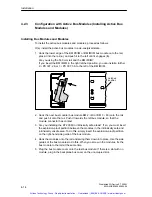
Plugging in Output Modules During Operation of an ET 200M Installation
!
Warning
When you insert output modules, uncontrolled system states may occur.
This is also the case when you plug in input/output modules at an angle onto the
bus module.
When you plug in an output module, the outputs set by the user program
immediately become active!
We recommend that you set the outputs in the user program to ”0” when you
remove an output module.
If modules are removed and plugged in incorrectly, neighboring modules may be
affected via the backplane bus!
4.2.4
After Installation
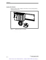
Assigning Slot Numbers
After installation you can assign a slot number to each module. This makes it
easier to assign the modules in the configuration table in STEP 7 or in COM
PROFIBUS. Table 4-4 shows the slot number assignment.
Table 4-4
Slot numbers for S7 modules
Slot Number
Module
Remarks
1
Power supply (PS)
1
–
2
IM 153-x
–
3
–
Not applicable
4
1st S7-300 module
Next to the IM 153-x on the right
5
2nd S7-300 module
–
...
...
11
8th S7-300 module
–
1
Use of the power supply is optional.
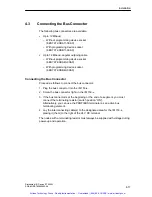
Unoccupied Slots
If you do not use all the slots in a configuration of an ET 200M with active bus
modules (perhaps reserving them for later), you must leave these slots free in the
STEP 7 and COM PROFIBUS configurations.
Artisan Technology Group - Quality Instrumentation ... Guaranteed | (888) 88-SOURCE | www.artisantg.com


