External Accessories
Slid ing Second ary Disconnects
A
DANGER
Hazardous Voltage.
Will cause severe injury or death.
Do not attempt to install Sliding
Disconnects with voltage present.
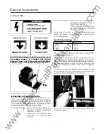
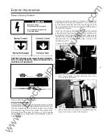
Sliding Secondary Disconnects
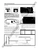
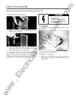
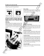
Sliding secondary disconnects provide electrical access to
the internal accessories and trip unit of a drawout con
structed SB breaker. They are installed along the sides of
the drawout elements such that the electrical connections
are made as the moveable drawout element is moved/
racked into the stationary drawout element.
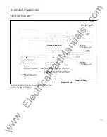
Secondary Disconnects and
Terminal Block Terminal Points
I 1
Motor Operator Power ( +)
Remote Close ( +)
Local Electnc Close (+)
Spr1ng Charge lndicat1on
Common Motor Operator
Shunt Tnp (
+)
Remote lnd1cat1on Open/Close
Common, Shunt Tr1p
Undervoltage Release
(
+)
Undervoltage Release (-)
Neutral Sensor ( +)
Neutral Sensor (-)
Electnc Close Interlock
ElectriC Close Interlock
Spare
Load Mon1tor Alarm ( +5V)
Fault lnd1cator A
Fault Indicator 8
Tr1 p Clock
Dig1tal Common
+ 1 2V (Yellow)
TX
Data (Green)
Common (Red)
RX
Data (Black)
u
u
(
"'
· ,
)
(
"'
,
)
c:::::=::::J
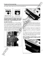
A breaker can be equipped with up to four secondary
disconnects, each with 1 2 terminal points. Each secondary
disconnect consists of an A and a B block. On the right side
of the stationary drawout element the A block is at the top
and the B block is at the bottom. They are reversed on the
left side: B at the top, A at the bottom. On the right side of
the moveable drawout element, the B block is at the top and
the A block is at the bottom. These are also reversed on the
left side: A at the top, B at the bottom. The blocks and
d rawout elements are keyed to p revent i mp roper
installation .
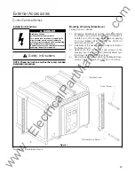
Disconnects must be affixed to stationary and moveable
drawout elements prior to racking-in the moveable element.
The secondary disconnects are attached with screws to
the stationary and moveable drawout elements.
u
D
Load
Load
Load
Load
(
"'
,
)
r 1
Auxiliary Sw1tch 4A
Auxil1ary Switch 4A
Aux1l1ary Sw1tch 48
Aux1l1ary Sw1tch 48
Aux1l1ary Sw1tch 5A
Auxiliary Switch 5A
Aux1l1ary Sw1tch 58
Auxiliary Sw1tch 58
Mon1tor Or Electronic Alarm Sw1tch Or Auxiliary Sw1tch 6 A
Mon1tor Or ElectroniC Alarm Sw1tch Or Aux1llary Sw1tch 6 A
Monitor Or ElectroniC Alarm Sw1tch Or Aux1hary Sw1tch 6 8
Mon1tor Or Electromc Alarm Sw1tch Or Auxlll3ry Switch 6 8
u
Auxiliary Sw1tch l A
Auxli1ary Sw1tch 1 A
Auxiliary Switch 1 B
Auxll13ry Sw1tch
I
8
Aux1l1ary Switch 2A
Auxiliary Sw1tch 2A
Auxiliary Sw1tch 28
Aux1l1ary Sw1tch 28
AUXIliary SwitCh 3A
Aux111ary Sw1tch 3A
Auxiliary Sw1tch 38
Aux111ary Switch 38
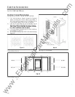
Control Terminals Identification
Term1na1 Blocks (F1xed Breakers)
Control Disconnects (Drawout Breakers)
65
www
. ElectricalPartManuals
. com

