background image

8/57

CC1B7865en

05.12.2002

HVAC Products

2. Type of unit

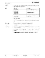
The type field is glued onto the housing. The type designation consists of operating
voltage and type reference of the unit.

Type of unit

Description

RWF40.000A97

RWF40.010A97 ¹·

Basic version with floating output

RWF40.001A97

RWF40.011A97 ¹·

With additional analog output

RWF40.002B97

RWF40.012B97 ¹·

With additional analog output and

RS-485 interface

¹· Packaging variants

G

The power supply must agree with the operating voltage given on the type field.

The measured value range and the analog inputs are factory-set.

ð

    Chapter 8 «Configuration»

Adapter frame ARG40

 for plants where the RWF32... predecessor model was used (for

conversion to RWF40...).

Bracket ARG41

 for mounting the RWF40... on 35 mm DIN rails conforming to

DIN 46277.

Dummy cover AVA10.200/109

 for covering control panel cutouts for the RWF40...

2.1 Type field

Location

Types

Factory setting

Accessories

Содержание RWF40.000A97

Страница 1: ...pressure control in connection with modulating or multistage burners User Manual The RWF40 controller and this User Manual are intended for use by OEMs which integrate the controller into their products CC1B7865en 05 12 2002 Siemens Building Technologies HVAC Products ...

Страница 2: ...2 57 CC1B7865en 05 12 2002 HVAC Products ...

Страница 3: ...ing modes 18 Low fire operation 18 High fire operation 18 Modulating burner floating output 18 Modulating burner analog output 19 2 stage burner floating output 19 2 stage burner analog output 20 Safety shutdown 20 Predefined setpoint 20 Setpoint changeover SP1 SP2 analog setpoint shift 21 Setpoint changeover SP1 external setpoint 22 Setpoint SP1 analog binary setpoint shift 23 External setpoint b...

Страница 4: ...nalog input 2 45 SCH2 scaling of standard signal range end analog input 2 46 SPL lower setpoint limit 46 SPH upper setpoint limit 46 OFF1 actual value correction for analog input 1 46 OFF2 actual value correction for analog input 2 46 OFF3 actual value correction for analog input 3 46 dF1 2nd order digital filter for analog input 1 46 dF3 1st order digital filter for analog input 3 only with RWF40...

Страница 5: ...er 53 Output 2 3 floating output 53 Output 4 limit comparator 53 Output 5 analog output option 54 Transducer supply 54 Interface RS 485 optional 54 General ratings 54 Measuring accuracy 55 Monitoring of measuring circuit 55 Environmental conditions 55 Current settings 56 Process data 56 Parameter level 56 Configuration level 57 11 11 1 11 1 1 11 1 2 11 1 3 11 1 4 11 1 5 11 2 11 2 1 11 2 2 11 2 3 1...

Страница 6: ...edback acting on the burner An external switch can be used to change it to a 2 position controller for the control of 2 stage burners The integrated thermostat function switches the burner on and off The thermostat relay output 1 can be used as a thermal reset limit thermostat conforming to DIN 3440 An adjustable response threshold is used to switch to a higher burner output high fire operation In...

Страница 7: ...ers or sections abc Footnote Footnotes are comments referring to specific parts of the text They consist of 2 parts 1 The markings in the text are arranged as continuous superscript numbers 2 The footnote text is placed at the bottom of the page and starts with a number and a period Action This symbol indicates that a required action is described The individual steps are indicated by an asterisk e...

Страница 8: ...ith additional analog output and RS 485 interface Packaging variants G The power supply must agree with the operating voltage given on the type field The measured value range and the analog inputs are factory set ð Chapter 8 Configuration Adapter frame ARG40 for plants where the RWF32 predecessor model was used for conversion to RWF40 Bracket ARG41 for mounting the RWF40 on 35 mm DIN rails conform...

Страница 9: ...from sources of electromagnetic fields such as variable speed drives or high voltage ignition transformers Relative humidity 95 noncondensing Ambient temperature range 20 50 C Storage temperature range 40 70 C 48 96 91 5 K6 PGM EXIT RWF40 112 Panel cut out to DIN 43 700 45 92 0 6 0 8 43 5 127 5 15 5 7865m01e 1200 3 1 Installation site and climatic conditions 3 2 Dimensions ...

Страница 10: ...roller housing G The unit must be installed with the seal so that no water or oil can penetrate the housing Insert the controller from the front into the panel cutout 7865z08 0200 At the rear of the panel push the fixing elements into the guide slots from the side or top The flat faces of the fixing elements must rest on the housing Place the fixing elements against the rear of the panel and tight...

Страница 11: ...essure cleaners The controller module can be removed from the housing for service The rules as per DIN EN 100 015 Protection of electrostatically sensitive devices must be observed for internal work on the controller No liability will be assumed for damage caused by electrostatic discharge 7865z09 0200 Press the ribbed surfaces together at top and bottom and pull out the controller module 3 5 Clea...

Страница 12: ...les as twisted and shielded cables and do not run them close to power cables or components Ground the shielding to the controller at one end to the TE terminal Earth the TE terminal of the controller to protective earth This cable must have a cross sectional area that is at least as large as that of the supply cables Earthing cables must be wired in a star configuration to a common earthing point ...

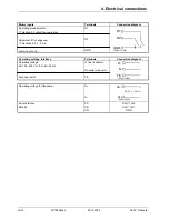
Страница 13: ...dard signals Input 2 External setpoint setpoint shifting for 0 1 k resistor or linearized standard signals Input 3 Outside temperature for Landis Staefa Pt1000 LG Ni1000 For potential free contacts Input 1 Operating mode changeover Input 2 Setpoint shifting changeover Output 1 Relay N O contact Output 2 Relay actuating device open Output 3 Relay actuating device closed Output 4 Relay N O contact D...

Страница 14: ...hermal reset limit thermostat to DIN 3440 Contact protection Varistor S07K275 Q14 pole Q13 N O contact Q14 P S Q13 7865a11 1199 Relay 2 Actuating device opens Contact protection RC unit Relay 3 Actuating device closes Contact protection RC unit Y1 N O contact Q common pole Y2 N O contact P S Y1 Q Y2 S P 7865a16 1099 Relay 4 Limit comparator Contact protection Varistor S07K275 K6 Q64 pole Q63 N O c...

Страница 15: ...DC 0 20 mA 4 20 mA I1 M1 I1 M1 7865a06 1099 Voltage input DC 0 1 V 0 10 V U1 M1 U1 M1 7865a07 1099 Analog input 2 setpoint and setpoint shift Terminals Connection diagram Resistance potentiometer Offset correction OFF2 XB6 start M6 slider M6 end M6 XB6 A S E 7865a08 1099 Current input DC 0 20 mA 4 20 mA XB6 M6 XB6 M6 7865a09 1099 Voltage input DC 0 1 V 0 10 V XU6 M6 XU6 M6 7865a10 1099 Analog inpu...

Страница 16: ...ft changeover ð Sections 5 4 1 5 4 4 Common ground D1 D2 GND D1 D2 GND 7865a12 1099 Operating voltage interface Terminals Connection diagram Operating voltage AC 100 240 V 10 48 63 Hz Technical earth L1 live conductor N neutral conductor TE L1 N TE 7865a18 1099 Operating voltage for transducer G G G G DC 24 V 30 mA 7865a14 1099 Serial interface RS 485 CA CB CG RxD TxD RxD TxD GND ...

Страница 17: ...dard signals Input 3 Outside temperature for Landis Staefa Pt1000 LG Ni1000 2 binary inputs for potential free contacts D1 Operating mode changeover D2 Setpoint shift changeover Transducer supply DC 24 V 30 mA short circuit proof Analog output optional Output 5 Analog output DC 0 10 V DC 0 20 mA 4 20 mA Serial interface RS 485 optional MOD bus protocol Technical earth TE Limit comparator Output 4 ...

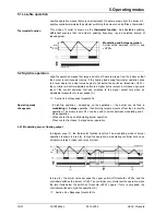
Страница 18: ...n adjustable threshold Q is exceeded A ð Section 5 6 Response threshold Q In high fire operation depending on the application the burner can be fired in modulating or 2 stage operation then burning larger amounts of fuel than in low fire operation The binary input D1 can be used to switch between modulating and 2 stage operation When contact is open Modulating burner operation When contact is clos...

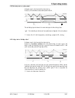
Страница 19: ...mostat function is active In area 2 a 2 position controller acts on the second stage via relay 2 open and relay 3 close by switching it into the circuit at the switch on threshold HYS1 and out of circuit at the switch off threshold HYS2 q A B q A I II 2 1 W HYS2 HYS1 HYS3 7865w06 1099 In area 3 the actual value exceeds the upper switch off threshold HYS3 and the controller shuts down the burner B ...

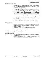
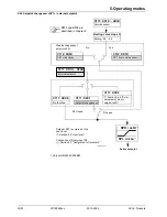
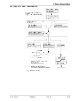
Страница 20: ...re the controller cannot monitor the actual value of the boiler temperature analog input 1 Safety shutdown will automatically be triggered to guard against overheating This also applies to the acquisition of the external setpoint at analog input 2 Burner off Floating output for closing the actuating device Self setting is ended Manual operation is ended The setpoint is preselected within preset li...

Страница 21: ...t changeover C111 XXX0 No function Setpoint SP2 SP2 via buttons C111 X6XX XAXX Analog setpoint shift SPL oLLo SPH oLHi C111 and C112 are described in chapter 8 Weather dependent setpoint shift No Yes D2 open D2 closed Active setpoint Setpoints SP1 and SP2 are entered on the user level Section 6 2 User level Connection of binary input D2 Section 4 2 Assignment of terminals 7865f05e 1202 1 1 Only wi...

Страница 22: ...nt shift C111 XXX1 Setpoint changeover C111 XXX0 No function C111 X1XX X5XX External setpoint SPL oLLo SPH oLHi C111 and C112 are described in chapter 8 Weather dependent setpoint shift No Yes D2 open D2 closed Active setpoint Setpoint SP1 is entered on the user level Section 6 2 User level Connection of binary input D2 Section 4 2 Assignment of terminals 7865f03e 1202 1 1 Only with RWF40 0X2B97 5...

Страница 23: ...X2 Binary setpoint shift C111 XXX0 No function C111 X6XX XAXX Analog setpoint shift SPL oLLo SPH oLHi C111 and C112 are described in chapter 8 Weather dependent setpoint shift No Yes D2 open D2 closed Active setpoint Values dSP and SP1 are entered on the user level Section 6 2 User level Connection of binary input D2 Section 4 2 Assignment of terminals dSP 0 0 7865f04e 1202 1 1 Only with RWF40 0X2...

Страница 24: ...nction C111 X1XX X5XX External setpoint SPL oLLo SPH oLHi D2 open D2 closed Active setpoint Values dSP and SP1 are entered on the user level Section 6 2 User level Connection of binary input D2 Section 4 2 Assignment of terminals dSP 0 C111 and C112 are described in chapter 8 7865f02e 1202 1 1 Only with RWF40 0X2B97 5 4 4 External setpoint binary setpoint shift ...

Страница 25: ...n addition with the RWF40 0X2B97 the lower working range limit oLLo and the upper working range limit oLHi protect the plant by ensuring that the minimum plant temperature will be observed Parameter P can be used to apply a parallel displacement to the heating curve G Each RWF40 must have its own separate outside sensor no parallel connection F This function has been optimized for space heating co...

Страница 26: ...dent setpoint is restricted by the setpoint limits SPH and SPL Setpoint C Outside temperature C HYS1 20 20 0 H smaller 10 10 SPL SPH H larger HYS3 7865d01e 1102 oLHi 1 oLlo 1 Only with RWF40 0X2B97 HYS1 is the switch on point for the burner and HYS3 is the switch off point As already described they act with the set shift relative to the weather dependent setpoint ð Section 5 2 1 Modulating burner ...

Страница 27: ...ching threshold HYS1 If the actual value increases integration is stopped If Qeff exceeds the preset response threshold Q can be adjusted on the parameter level this causes the second stage of the burner to switch on or in the case of a floating controller modulating controller the actuating device to open If the actual boiler temperature reaches the required setpoint Qeff is reset to 0 Temperatur...

Страница 28: ...in limit value This limit is calculated as follows Limit value 2 HYS1 HYS3 In that case response threshold Q is inactive independent of the operating mode and the controlled variable temperature or pressure Operating mode Modulating floating output HYS1 3 K HYS3 5 K w 60 C Limit value 2 3 5 2 8 16 K At an actual value below 44 C the heating up procedure immediately starts in high fire operation in...

Страница 29: ...nd the parameter values for the various levels The setpoint and parameters are shown in the lower section of the display green BASIC DISPLAY USER LEVEL PARAMETER LEVEL CONFIGURATION LEVEL 1 1 1 Min 2 s Min 2 s Min 2 s or time out approx 30 s 7865f08e 1299 1 After using PGM to step through all the parameters of a level automatic return occurs after the last parameter has been confirmed Assignment o...

Страница 30: ...anual operation self setting the user parameter and configuration levels can be activated from here 503 639 Limit comparator Increase value EXIT button Manual operation 2 stage operation PGM button Actuating device OPENS 2nd stage Actuating device CLOSES 1st stage Release of burner Actual value display red Setpoint display green 7865p02e 1202 Decrease value 6 1 Basic display 6 1 1 Meaning of the d...

Страница 31: ... High fire operation F If there is no action by the operator the controller will automatically return to the basic display after about 30 seconds This level is started from the basic display Setpoints SP1 and SP2 dSP can be altered and the analog inputs E2 external setpoint setpoint shift and E3 outside temperature can be displayed To alter SP1 SP2 or dSP Change to the user level with PGM Alter se...

Страница 32: ...0 10 0 PGM Depending on the configuration of binary input 2 dSP Sp2 Measurement of the outside temperature via analog input 3 Measurement of the external setpoint or a setpoint shift via analog input 2 Display depends on code 111 65 0 65 0 60 3 70 0 10 0 SP 1 EXIT SP 2 User level EXIT EXIT 7865f06e 1199 ...

Страница 33: ...ting device will be set to 0 until another entry with the buttons is made Manual operation can only be activated if the thermostat function has set relay 1 active If the thermostat function sets relay 1 inactive during manual operation manual operation is terminated Press EXIT for 5 seconds Press briefly Relay 2 is active relay 3 is inactive Analog output optional delivers DC 10 V The actuating de...

Страница 34: ...as stopped Accept the parameters that have been determined by pressing press the button for at least 2 seconds F It is not possible to start tunE in manual operation or thermostat operation Press PGM Available units C F and for standard signals PGM 7865z11 1199 6 2 4 Start self setting 6 2 5 Display of the software version and of unit of actual value ...

Страница 35: ...g Accept entry by pressing PGM or Cancel entry by pressing EXIT F After 2 seconds the set value will automatically be accepted The value can only change within the permissible value range ð Chapter 7 Parameter settings The settings made here are those required for commissioning a specific installation and therefore need hardly ever be altered later on acquisition of measured value or type of contr...

Страница 36: ...tching differential at the edges for the limit comparators ð Chapter 8 2 C112 limit comparator controller type setpoint SP1 locking Proportional band 1 Pb 1 0 1 999 9 digit 10 Affects the P response of the controller Derivative time dt 0 9999 s 80 Affects the D response of the controller Within dt 0 the controller has no D response For modulating controllers dt rt 4 or 0 must be entered Integral a...

Страница 37: ...hold for burner stage II 1 H Y S 1 0 199 9 digit 5 ð Section 5 5 1 Heating curve slope Switch off threshold stage II 1 H Y S 2 0 HYS3 digit 3 ð Section 5 2 High fire operation Upper switch off threshold 1 H Y S 3 0 999 9 digit 5 ð Section 5 2 High fire operation Response threshold q 0 999 9 0 ð Section 5 6 Response threshold Q Heating curve slope H 0 4 1 ð Section 5 5 1 Heating curve slope Paralle...

Страница 38: ...ndard signal DC 0 10 V G Standard signal DC 0 1 V H Pt RhPt S i Pt RhPt R j Pt RhPt B L Analog input 2 No function 0 External setpoint 1 kW resistance potentiometer 1 External setpoint DC 0 20 mA 2 External setpoint DC 4 20 mA 3 External setpoint DC 0 10 V 4 External setpoint DC 0 1 V 5 Analog setpoint shift 1 kW resistance potentiometer 6 Analog setpoint shift DC 0 20 mA 7 Analog setpoint shift D...

Страница 39: ...3 0200 Analog input 3 No function 0 Outside sensor Landis Staefa Pt1000 2 wire IEC 751 1 Outside sensor Ni1000 2 wire DIN 43760 2 Outside sensor LG Ni1000 2 wire 3 Function of binary input D2 No function 0 Setpoint changeover 1 Setpoint shift binary 2 Factory setting 9 0 3 0 ...

Страница 40: ...controller DC 0 20 Ma 1 Modulating controller DC 4 20 mA 2 Modulating controller DC 0 10 V 3 Setpoint SP1 SP1 via buttons 0 SP1 with outside sensor analog input 3 must be configured 1 Locking No locking 0 Locking of configuration level 1 Locking of parameter level 2 Locking of buttons 3 G Locking of the buttons can be entered only once and adapted with PGM Then all button operations will be locked...

Страница 41: ...w Measured value 7865d10e 0300 Output 4 Like lk1 but inverted switching function AL HYSt w Measured value 7865d09e 0300 Output 4 HYSt switching differential of the window edges AL interval from setpoint half the window width Lower limit signaling Function Relay inactive when measured value setpoint limit value Example w 80 C AL 10 HYSt 2 Measured value rising Relay K6 switches on at 71 C Measured ...

Страница 42: ... Parameter settings Upper limit signaling Function Relay inactive when measured value setpoint limit value Example w 80 C AL 10 HYSt 2 Measured value rising Relay K6 switches off at 91 C Measured value falling Relay K6 switches on at 89 C AL HYSt w Measured value 7865d05e 0300 Output 4 Like lk5 but inverted switching function AL HYSt w Measured value 7865d06e 0300 Output 4 Function Ik4 Function Ik...

Страница 43: ...ctive when measured value limit value Example AL 50 HYSt 2 Measured value rising Relay K6 switches on at 51 C Measured value falling Relay K6 switches off at 49 C AL HYSt Measured value 7865d07e 0300 Output 4 Like lk7 but inverted switching function AL HYSt Measured value 7865d08e 0300 Output 4 HYSt switching differential AL limit value ð Chapter 7 Parameter settings Function Ik7 Function Ik8 ...

Страница 44: ...600 Bd 2 One decimal place degrees Fahrenheit 9600 Bd 3 No decimal place degrees Celsius 19200 Bd 4 One decimal place degrees Celsius 19200 Bd 5 No decimal place degrees Fahrenheit 19200 Bd 6 One decimal place degrees Fahrenheit 19200 Bd 7 No decimal place degrees Celsius 4800 Bd 8 One decimal place degrees Celsius 4800 Bd 9 No decimal place degrees Fahrenheit 4800 Bd A One decimal place degrees F...

Страница 45: ...a measured value of 80 C 0 mA 20 mA 0 C 80 C 100 C Value range 1999 9999 digit Factory setting 100 digit SCL2 20 0 mA corresponds to a measured value of 20 C as already described Value range 1999 9999 digit Factory setting 0 digit 8 3 1 SCL scaling of standard signal range start analog input 1 Example 8 3 2 SCH scaling of standard signal range end analog input 1 Example 8 3 3 SCL2 scaling of stand...

Страница 46: ...wire circuit Value range 1999 9999 digit Factory setting 0 digit Measured value Offset Displayed value 294 7 0 3 295 295 3 0 3 295 Value range 1999 9999 digit Factory setting 0 digit Value range 1999 9999 digit Factory setting 0 digit Value range for filter time constant 0 100 s Factory setting 1 seconds 8 3 11 dF3 digital filter of 1st order for analog input 3 only with RWF40 0X2B97 Value range f...

Страница 47: ...d hysteresis 3 If switch off threshold SP Hyst3 oLHi exceeds the upper working range limit the switch off threshold will be replaced by the upper working range limit The setpoint does not change SP 90 Hyst3 5 oLHi 93 ð Switch off threshold 93 Current setpoint 90 If the setpoint lies above the upper working range limit the setpoint and switch off threshold will be replaced by the upper working rang...

Страница 48: ... settings Controller Controlled system Y W X 7865f09e 1199 The tunE function uses 2 different methods that are automatically selected depending on the dynamic state of the actual value and the deviation from the setpoint at the start tunE can be started from within any dynamic actual value sequence If there is a large difference between actual value and setpoint when tunE is activated a switching ...

Страница 49: ...ctual value filtering that is optimized for this controlled system High fire operation in the modulating burner mode The thermostat function relay 1 must be constantly activated otherwise tunE will be canceled and no optimized controller parameters will be adapted The above mentioned actual value oscillations during self setting may not exceed the upper threshold of the thermostat function increas...

Страница 50: ...ir correction The response to a setpoint change is shown here for a 3rd order controlled system for a PID controller The method used for adjusting the controller parameters can however also be applied to other controlled systems A favorable value for dt is rt 4 PB too small PB too large t x w 7865d17 1099 t x w 7865d15 1099 rt dt too small rt dt too large t x w 7865d16 1099 t x w 7865d14 1099 Opti...

Страница 51: ...erature C111 and the measured value is called up the actual value display red shows 1999 flashing G Overrange or underrange on analog input 3 Outside temperature is not measured The weather dependent setpoint is inactive Check electrical connections for open circuit of sensors 1999 SP E 7865p09 0200 When analog input 2 is configured C111 and the measured value is called up the process value displa...

Страница 52: ...F NiCr Ni K 200 1372 C 328 2502 F Cu CuNi T 200 400 C 328 752 F NiCrSi NiSi N 100 1300 C 148 2372 F Pt RhPt S 0 1768 C 32 3214 F Pt RhPt R 0 1768 C 32 3214 F Pt RhPt B 0 1820 C 32 3308 F Only with RWF40 0X2B97 Cold junction temperature Internal Signal Internal resistance Ri Voltage drop DUe DC 0 10 V Ri 2 MW DC 0 1 V Ri 2 MW DC 0 20 mA DUe 1 V DC 4 20 mA DUe 1 V Sampling time 210 ms Resistance mea...

Страница 53: ...uts 1 analog output optional and a transducer supply are provided as standard Relay output N O contact Contact rating AC 24 240 V 2 A at p f cos j 0 6 Contact life 2 x 10⁵ switching cycles at rated load Internal contact protection Varistor S07K275 2 relay outputs N O contacts with a common pole for actuating device open close Contact rating AC 24 240 V 2 A at cos j 0 6 Contact life 2 x 10⁵ switchi...

Страница 54: ...99 Galvanic separation between supply voltage analog inputs and outputs ð Section 4 3 Galvanic separation Weight approx 430 g Data backup EEPROM Operating voltage AC 100 240 V 10 48 63 Hz Power consumption approx 5 VA Electrical connection at the rear via plug in screw terminal strips angled at 45 Electrical safety to EN 60730 Case mounting depth 130 mm plastic body with rear panel self extinguish...

Страница 55: ...C 0 10 V DC 0 20 mA DC 4 20 mA X X is not detected X is detected and 1999 appears on the display ð Chapter 10 What to do if Permissible ambient temperature range 20 50 C short time up to 60 C Permissible storage temperature range 40 70 C Climatic conditions Relative humidity 95 noncondensing Degree of protection to EN 60529 Front IP 65 Rear IP 20 Electromagnetic compatibility EMC To NAMUR recommen...

Страница 56: ...f limit comparator 1 AL 1999 9999 digit 0 Switching differential for limit comparator 1 HYSt 0 999 9 digit 1 Proportional band 1 Pb 1 0 1 999 9 digit 10 Derivative time dt 0 9999 s 80 Integral action time rt 0 9999 s 350 Dead band neutral zone 1 db 0 999 9 digit 1 Actuator running time tt 10 3000 s 15 s Switch on threshold burner stage II 1 H Y S 1 0 199 9 digit 5 Switch off level stage II 1 H Y S...

Страница 57: ...H 100 Actual value correction analog input 1 1 OFF1 0 Actual value correction analog input 2 1 OFF2 0 Actual value correction analog input 3 1 OFF3 0 Filter time constant for digital filter analog input 1 dF1 1 Filter time constant for digital filter weather dependent setpoint shift dF3 2 1278 Lower working range limit 1 oLLo 2 1999 Upper working range limit 1 oLHi 2 9999 Bus watchdog timer dtt 2 ...

Отзывы: