background image

Technical Instructions 

RWD62U Universal Controller 

Document Number 155-737 
January 14, 2005 


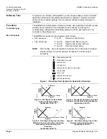
P+I Limiter Function 

NOTE: 

In the following 
illustrations, the 
heating and cooling 
outputs are D.A. 
Outputs can be 
reversed. 

TH0794R1

X1

Y2

Y1

Temp.

Y

X2


Figure 9.  P+I Limiter Function. 

The limiter function with P+I control 
enables absolute (or relative) maximum 
or minimum limitation of the supply air 
temperature (X2). 

When the value drops below or exceeds 
the limiter setpoint, the limiter function 
controls and takes priority over the main 
setpoint. 

Remote Setpoint 

NOTE: 

You cannot select 
the remote setpoint 
auxiliary function in 
Night mode. 


X1

Y2

Y1

Temp.

Y

X2

TH0793R1


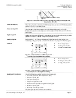
Figure 10.  Remote Setpoint. 

A remote setpoint transmitter (QAA25U), 
connected to X2 and configured 
accordingly, enables setpoint 
adjustment. 

Active measurement from 0 to 10 Vdc 
corresponding adjustable range from  
–100 to 8000 units 

Passive measurement from 0 to 1000 


corresponding adjustable range from  
–100 to 8000 units 

Cascade Control 

TH0794R1

X1

Y2

Y1

Temp.

Y

X2


Figure 11.  X2 Supply Air Temperature 

Sensor. 


You can select the P+I/P+I room/supply 
air temperature cascade control. In this 
case, the virtual P+I room temperature 
controller determines the setpoint within 
the limiter setpoints for the P+I supply air 
temperature controller. 

Maximum Priority 

NOTE: 

You cannot select 
the maximum priority 
auxiliary function in 
Night mode. 

TH0795R1

X2

Y2

Y1

Temp.

Y

X1


Figure 12.  Maximum Priority, 

Cooling. 

If the value (0 to 10V) of the input X2 is 
greater than the calculated output of the 
cooling sequence, the output will use the 
X2 input value as output value. This is 
active even when the controller is 
working with the heating sequence. 

Setpoint Compensation 

TH0796R1

X2

Y1

Temp.

Y

X1


Figure 13.  Setpoint Compensation. 

The temperature setpoint X1 is shifted 
by the temperature as measured at 
sensor X2. 

Configuration of the RWD62U defines 
the influence on setpoint X1. 

The example shows the room air 
temperature setpoint as shifted by the 
outside temperature. 

Page 6 


Siemens Building Technologies, Inc. 

Содержание RWD62U

Страница 1: ... and Siemens Building Technologies program software NOTE For complete supporting technical documentation including training presentations see www us sbt siemens com hvp components Features Stand alone electronic temperature controller with P or P I response 24 Vac operating voltage Control application selectable via Application Number Active input scale can be selectable Limit and direction of the...

Страница 2: ... 1 Weight RWD62U Controller 10 4 oz 295 grams With packaging 12 24 oz 347 grams Analog Inputs X1 X2 Siemens Ni 1000 ohm 32 F 0 C Controller measuring range 58 F to 302 F 50 C to 150 C Maximum cable length for 14 AWG Maximum 984 ft 300 m Pt 1000 ohm at 32 F 0 C Controller measuring range 4 F to 356 F 20 C to 180 C Maximum cable length for 14 AWG Maximum 984 ft 300 m Analog voltages For measured var...

Страница 3: ...B Series 310 lb in Non Spring Return Actuators GBB Series 177 lb in Non Spring Return Actuators 155 176P25 155 177P25 GEB Series 132 in lb Non Spring Return Actuators 155 318P25 GCA Series 142 in lb Spring Return Actuators 155 173P25 155 174P25 155 175P25 GMA Series 62 in lb Spring Return Actuators 155 315P25 SKD Valve Actuator with proportional input 155 180P25 SKB SKC Valve Actuator with proport...

Страница 4: ... or Y1 and Y2 Direct and direct acting NOTE Direct Acting As air temperature increases the control output increases Reverse Acting As air temperature increases the control output decreases TH0599R3 TEMPERATURE SENSOR AIR DAMPER ACTUATOR HEATING COIL COOLING COIL HEATING OR COOLING COIL TWO PIPE FAN OR PUMP TIME CLOCK REMOTE SET POINT UNIT OUTSIDE AIR SENSOR Figure 1 Frequently Used Symbols in Appl...

Страница 5: ...D1 input Analog Outputs Each output Y1 Y2 can be configured for either reverse or direct acting The modulating voltage output Y controls the devices requiring a 0 to 10 Vdc signal Example X1 Y2 Y1 Temp Y TH0791R1 Figure 7 Constant Volume with Temperature Control Direct Acting Reverse Acting X1 Room temperature Y1 Heating direct action Y2 Cooling reverse action X1 Y2 Y1 Temp Y TH0811R1 Figure 8 Con...

Страница 6: ...corresponding adjustable range from 100 to 8000 units Cascade Control TH0794R1 X1 Y2 Y1 Temp Y X2 Figure 11 X2 Supply Air Temperature Sensor You can select the P I P I room supply air temperature cascade control In this case the virtual P I room temperature controller determines the setpoint within the limiter setpoints for the P I supply air temperature controller Maximum Priority NOTE You cannot...

Страница 7: ... contact between terminals D1 and M can be used to implement setpoint changeover for day night operation When the contact is open the setpoints for day operation are selected When the contact is closed the setpoints for night operation are selected During the night mode the following auxiliary functions are disabled remote setpoint absolute relative limiter setpoint compensation and maximum priori...

Страница 8: ...62U Universal Controller LCD The LCD shows the following information for normal operation Current operating values maximum four digits Current setpoints day night Application number Control sequencing diagram Auxiliary input value Selected auxiliary function Operating Buttons The controller has three operating buttons for the following functions The SELECT button is used to enter or save the value...

Страница 9: ...ansformers with double insulation they must be designed for 100 duty When using several transformers in one system the connection terminals G0 ground must be galvanically connected Supplying voltages above 24 Vac to low voltage connections may damage or destroy the controller or any other connected devices Connections to voltages exceeding 24 Vac endanger personal safety The ARG62 21 Protective Ho...

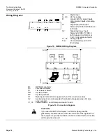
Страница 10: ...gram TH0801R1 Y1 G Y1 S1 D1 GO Y B M B M X1 X2 M M Y2 Y2 GO G Y X2 X1 M M M GO G 24 V SN 24 V SP N1 TOOL PC G G N1 RWD62U controller PC Personal computer S1 Time clock or switch SN System neutral SP System potential X1 Main input Termination G appears when X1 is an active sensor X2 Auxiliary input or remote setpoint Termination G appears when X2 is an active sensor Y1 Y2 Valve actuator 1 and 2 Dam...

Страница 11: ...tive owners 2005 Siemens Building Technologies Inc Siemens Building Technologies Inc 1000 Deerfield Parkway Your feedback is important to us If you have comments about this document please send Dimensions In Inches Millimeters TH0802R1 5 12 130 3 50 89 4 37 111 2 22 56 5 1 89 47 9 1 22 31 0 16 4 0 16 4 4 17 106 1 80 45 7 Figure 20 RWD62U Controller Dimensions TH0745R1 5 91 150 7 87 200 2 41 61 2 F...

Отзывы: