RWD62U Universal Controller
Technical Instructions
Document Number 155-737
January 14, 2005
O
u
tput
V
o
lt
age
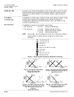
Y2
Setpoint
Temp.
Y1
TH0790R1
Figure 6. Two Direct Acting Cool or Two Reverse Acting Cool Sequences
(Application 50 to 59).
Universal Input X1
The primary input for a Siemens Ni 1000 temperature sensor, a Pt 1000 temperature
sensor, or a 0 to 10 Vdc active input.
Universal Input X2
The secondary input for a Siemens Ni 1000 temperature sensor, a Pt 1000
temperature sensor, an active/passive remote setpoint transmitter, or a 0 to 10 Vdc
active input.
Digital Input D1
Selects the day/night changeover. Changeover occurs via potential-free dry contacts
between D1 and M. Typically, a time clock controls D1 input.
Analog Outputs
Each output (Y1, Y2) can be configured for either reverse or direct acting. The
modulating voltage output (Y…) controls the devices requiring a 0 to 10 Vdc signal.
Example
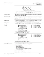
X1
Y2
Y1
Temp.
Y
TH0791R1
Figure 7. Constant Volume with Temperature
Control, Direct Acting/Reverse Acting.
X1 Room
temperature
Y1
Heating, direct action
Y2
Cooling, reverse action
X1
Y2
Y1
Temp.
Y
TH081
1R1
Figure 8. Constant Volume with Temperature
Control, Reverse Acting/Direct Acting.
X1 Room
temperature
Y1
Heating, reverse action
Y2
Cooling, direct action
Auxiliary Functions
One of the following auxiliary functions can be selected:
•
P+I limiter (Absolute, #x2 and Relative, #x3)
•
Remote setpoint, #x1
•
Cascade control, #x5
•
Setpoint compensation, #x4
•
Winter/summer operation, Digital #x6, Analog #x7
•
Maximum priority, #x8
•
Main loop 0 to 10V input, #x9
Day and night operation mode is also available.
Siemens Building Technologies, Inc.
Page 5

