background image


Electrical installation 

  Ensure that the local regulations for electrical installa-

tions are complied with 

  The connecting terminals are located under the flexi-

ble plastic cover 

  Make wiring according to the plant documentation. If 

not available, use the connection diagrams contained 
in these Installation Instructions 

  Observe the permissible cable lengths 

  Switch on power only when commissioning the con-

troller 

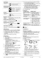
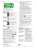
Settings 

33

37P

0

1

3

4

5

1

2

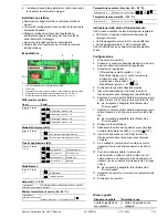
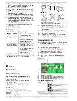
LED for test mode / fault / normal operation 

DIP switch block  

Setting slider for minimum charging temperature 

Potentiometer for loading temperature (40…90 °C) 

Potentiometer for maximum temperature (40…130 °C) 

Switching differential: 

Where?  

What? 

1 2 


  Switching differential = 8 K 

DIP switch block, 
switches no. 1 and 2 


  Switching differential = 1 K 


  Switching differential = 4 K 


  Switching differential = 2 K 

Operating mode (B2): 


With minimum charging temperature 

DIP switch block, 
switch no. 3  


Without minimum charging temperature 

Application type (B3): 

4 5 


  Applications 6, 7 

2 Exchangers (

t) 

DIP switch block, 
switches no. 4 and 5 


  Application 5 

2 Collectors (

t) 


  Applications 3, 4 

Bypass (°C) 


  Applications 1, 2 

Standard  

Test mode: 


Test mode 

DIP switch block, 
switch no. 6 


Normal operation  

Setpoint (1…30 K): 

Temperature 
setting slider  

Temperature differential required between the two 
plant elements 

Minimum charging temperature (30…80 °C): 

Setting slider 3 

When switch no. 3 is set to  


Absolute (load) temperature (40…90 °C): 

Potentiometer 4  

Switches no. 4 and 5 are set to  


  or  


Maximum temperature (40…130 °C): 

Potentiometer 5  

Switches no. 4 and 5 are set to 


Indication of operating state 

The red LED indicates the controller’s operating state: 

  LED lit: Mains voltage present (normal operation)  

  LED flashes fast (4 Hz): In test mode 

  LED flashes slow (1 Hz): Fault (B2) 

The LED is also visible when the cover is fitted. 


Commissioning 

1.  Remove housing cover. 
2.  Lift flexible plastic cover so that you can access the 

setting elements. 

3. Make 

the 

settings: 


Switching differential (switches no. 1 and 2) 


Operating mode (with / without minimum charging 
temperature, switch no. 3) 


Application type (switches no. 4 and 5)  


Test mode (switch no. 6 = 

 ON) 

4.  Replace flexible plastic cover. 
5.  Switch power on. LED for the operating state must 

flash (test mode). 

6.  Move temperature setting slider to the minimum 

value (<5 K) to prove contact Q1–Q3 

  If response is wrong, refer to “Troubleshooting” 

7.  Move temperature setting slider to the maximum 

value (>25 K) to prove contact Q4–Q6. 

  If response is wrong, refer to “Troubleshooting” 

8.  Switch power off. 
9.  Switch controller back to normal operation (set 

switch no. 6 to 

 OFF).  

10.  Switch power on. LED for the operating state must 

light up (normal operation). 

11.  If a remote setting unit is used, set the controller’s 

temperature setting slider to EXT. 

12.  First, set temperature setting slider to the minimum 

value, then to the maximum value: Observe the con-
trol. The response may neither be too fast nor too 
slow. 

  If response is wrong, refer to “Troubleshooting” 

13.  Adjust the setpoint with the temperature setting 

slider. 

14.  Replace housing cover. 

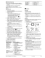
Troubleshooting  

Wrong response 

Possible causes 

Regulating units do not 
respond 

  Regulating units not con-

nected 

  No power supply 

Regulating units travel 
in the wrong direction 

 Controller terminals incor-

rectly wired 

  Controller and external sen-

sor mixed up 

 Sensor not connected 

Regulating units re-
main in one of their end 
positions 

  Temperature setting slider is 

set to EXT and there is no 
remote setting unit con-
nected 

  External sensor not con-

nected or short-circuit 

Control response too 
slow 

  Reduce switching differential 

Control is unstable 

 Increase switching differen-

tial 


Siemens Switzerland Ltd / HVAC Products 

CE1G3337xx 

23.11.2004 

3/16


Содержание rle127

Страница 1: ...sten 5 Rohrleitung bzw System wieder auffüllen 6 Der externe Temperaturfühler ist nach seiner Mon tageanleitung zu montieren Elektrische Installation Örtliche Vorschriften für Elektroinstallationen beach ten Anschlussklemmen sind unter der flexiblen Kunststoff abdeckung Anschlussklemmen entsprechend den Anlagendoku menten verdrahten Wenn diese fehlen Anschluss schaltpläne in dieser Anleitung beach...

Страница 2: ...rtgeber angeschlossen muss der Temperatur Einstellschieber auf EXT gestellt werden 12 Temperatur Einstellschieber zuerst auf Minimalwert stellen dann auf Maximalwert Regelung beobachten sie darf weder zu schnell noch zu träge reagieren bei falscher Reaktion siehe Abschnitt Fehler suche 13 Sollwert am Temperatur Einstellschieber einstellen 14 Deckel wieder montieren Fehlersuche Falsches Ergebnis Mö...

Страница 3: ...shes slow 1 Hz Fault B2 The LED is also visible when the cover is fitted Commissioning 1 Remove housing cover 2 Lift flexible plastic cover so that you can access the setting elements 3 Make the settings Switching differential switches no 1 and 2 Operating mode with without minimum charging temperature switch no 3 Application type switches no 4 and 5 Test mode switch no 6 ON 4 Replace flexible pla...

Страница 4: ...6 Potentiomètre de réglage de la température maximale 40 130 C Différentiel Où régler Que régler 1 2 Différentiel 8 K Bloc de commutateurs DIP commutateurs 1 et 2 Différentiel 1 K Différentiel 4 K Différentiel 2 K Mode de fonctionnement B2 3 Avec température minimale de charge Bloc de commutateurs DIP commutateur 3 Sans température minimale de charge Application B3 4 5 Applications 6 7 2 échangeur...

Страница 5: ...s le câblage de la sonde La régulation réagit trop lentement Réduire le différentiel La régulation est instable Augmenter le différentiel sv Svenska Montering Monteringsplats Max tillåten omgivningstemperatur 50 C Vid användning i värmekälla I den varmaste delen Vid användning i värmeförbrukare I den kallaste delen Vid användning i solkollektorer Direkt vid öppningen Montering Montering sker med d...

Страница 6: ...ft sätt omkopplare 6 på 10 Slå på matningsspänningen Lysdioden för driftindi kering måste lysa Normaldrift 11 Om en yttre börvärdesomställare finns ansluten skall temperaturskjutreglaget sättas på EXT 12 Sätt temperaturskjutreglaget först på min värdet och sedan på max värdet Kontrollera regleringen Den får varken vara för snabb eller för trög Vid felaktig reaktion se avsnitt Felsökning 13 Inställ...

Страница 7: ... rosso visualizza lo stato d impiego del regolatore LED acceso tensione d alimentazione presente impiego normale LED lampeggiante veloce 4 Hz in modalità test LED lampeggiante lento 1 Hz anomalia B2 Il LED è visibile anche a copertura flessibile plastica chiusa Configurazione 1 Rimuovere il coperchio 2 Sollevare la copertura flessibile plastica in modo da poter accedere agli elementi di regolazion...

Страница 8: ...instalacji elektrycznych Zaciski podłączeniowe umieszczone są pod elastyczną pokrywą z tworzywa sztucznego Okablowanie wykonać zgodnie z dokumentacją instalacji Jeśli jest ona niedostępna wykorzystać schematy połączeń przedstawione w niniejszej instrukcji Przestrzegać dopuszczalnych długości przewodów Zasilanie załączać dopiero przy uruchomieniu Nastawy 3337P0 1 3 4 5 1 2 1 Dioda LED wskazująca tr...

Страница 9: ...ze Brak zasilania Urządzenie wykonawcze przemieszcza się w złym kierunku Błędnie okablowane zaciski regulatora Zamieniony regulator i zewnętrzny czujnik temperatury Czujnik niepodłączony Urządzenie wykonawcze pozostaje w jednej z krańcowych pozycji Suwak nastawczy ustawiony w pozycji EXT i niepodłączony zdalny zadajnik Czujnik zewnętrzny niepodłączony lub zwarcie Zbyt długi czas odpowiedzi Zmniejs...

Страница 10: ...e operación con sin temperatura de carga minima interruptor 3 Tipo de aplicación interruptores 4 y 5 Modo test interruptor 6 ON 4 Colocar nuevamente la cubierta de plástico 5 Conectar la alimentación El LED para el estado de funcionamiento debe parpadear modo test 6 Mover el cursor deslizante de temperatura al valor mínimo 5 K para probar los contactos Q1 Q3 Si la respuesta es errónea ver Tabla de...

Страница 11: ...4 K Koblingsdifferens 2 K Driftsform B2 3 Med min ladetemperatur DIP switch blok kontakt 3 Uden min ladetemperatur Applikationstype B3 4 5 Applikation 6 og 7 2 varmevekslere t DIP switch blok kontakt 4 og 5 Applikation 5 2 kollektorer t Applikation 3 og 4 Bypass C Applikation 1 og 2 Standard Test mode 6 Test mode DIP switch blok kontakt 6 Normaldrift Setpunkt 1 30 K Temperaturindstil lingsskyder N...

Страница 12: ...Απευθείας σύνδεση στην έξοδο Τοποθέτηση Ο ελεγκτής θερµοκρασίας εµβάπτισης είναι σχεδιασµένος για να χρησιµοποιείται µέσα σε θήκη ασφαλείας ιαδικασία 1 Αδειάστε το δοχείο Ζ Ν Χ 2 Επιλέξτε µία από τις παρακάτω θέσεις συναρµολόγησης 3333Z02 max 15 max 15 Ο ελεγκτής δεν πρέπει να συναρµολογηθεί ανάποδα και το καλώδιο δεν πρέπει να το περάσετε από πάνω Tο ελάχιστο µήκος εµβάπτισης πρέπει να είναι 60 m...

Страница 13: ...θετηθεί στο EXT και δεν είναι συνδεδεµένο το τηλεχειριστήριο Το εξωτερικό αισθητήριο δεν είναι συνδεδεµένο ή υπάρχει βραχυκύκλωµα Η ανταπόκριση του ελέγχου είναι πολύ αργή Μειώστε την τιµή του διαφορικού Οι έλεγχος είναι ασταθής Αυξήστε την τιµή του διαφορικού ροµέας επιλογής no 3 Όταν ο µικρό διακόπτης no 3 είναι στη θέση Επιθυµητή θερµοκρασία από λέβητα 40 90 C Ποτενσιόµετρο no 4 Όταν οι µικρό δ...

Страница 14: ...e control normalmente abierto fr Français da Dansk B2 B3 Sondes de température B2 B3 Temperaturfølere L N Tension d alimentation 230 V L N Driftsspænding AC 230 V M Masse M Jord R1 Entrée du potentiomètre de consigne à distance R1 Indgang for ekstern referencegiver Q1 Q4 Entrée du contact de commande Q1 Q4 Indgang for styrekontakt Q2 Q5 Sortie du contact de commande normalement fermé Q2 Q5 Udgang ...

Страница 15: ... źródło ciepła np kocioł N1 Tauchtemperaturregler RLE127 N1 Zanurzeniowy regulator temperatury RLE127 R1 Fernsollwertgeber BSG21 1 R1 Zdalny zadajnik BSG21 1 Y1 Stellantrieb für Umschaltventil Y1 Siłownik zaworu przełączającego en English es Español B2 External temperature sensor heat source B2 Sonda de temperatura externa fuente de calor B3 External temperature sensor B3 Sonda de temperatura exte...

Страница 16: ...mensioni 3334M01 125 72 5 51 13 5 152 61 150 251 5 9 13 G A 29 Masse in mm Dimensions in mm Dimensions en mm Mått i mm Dimensioni in mm Wymiary w mm Dimensiones en mm Mål i mm ιαστάσεις σε mm 2004 Siemens Building Technologies Siemens Switzerland Ltd HVAC Products CE1G3337xx 23 11 2004 16 16 ...

Отзывы: