

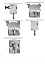


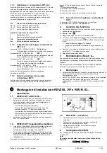


7 Finish
mounting of REV-R.03…
a) Switch off power
b) Mark location where REV-R.03… is currently fixed
c)
If necessary loosen wiring
d) Mount receiver at location marked before according Fig. 12 to
14, wire completely and close housing
e) Switch on power
DIP-switch Configuration and functional check REV200…RF
1 Configuration
1.1.
Calibrating the sensor:
DIP-switch 9
After activating the DIP-switch the
CAL
symbol will be shown and the
actual room temperature currently measured will flash. With pressing
the
+
can now be recalibrated by a maximum
± 2 °C
. To store
the recalibration, press the set button (also refer to Fig.
11/F
).
1.1.2 Setpoint limitation: DIP-switch 3
There are 2 setting choices available:
OFF. 3...29 °C (factory setting) or ON 16…29 °C
To store press the set button (also refer to Fig.
11/B
)
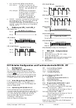
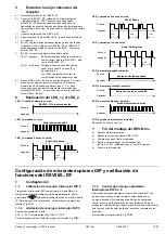
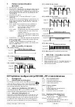
1.1.3 Optimum on; DIP switches 6 to 8
Optimum on brings forward the switch on point P.1 such that the
selected set value will be reached at the desired time. The setting
depends on the type of control system, that is, on heat transmission
(piping system, radiators), building dynamics (building mass,
insulation) and heating output (boiler output, flow temperature).
(Also refer to Diagram in Fig.
11/E
)
OFF
No effect (standard setting)
¼ h/°C
For fast controlled systems
½ h/°C
For medium controlled systems
1 h/°C
For slow controlled systems
Legend to diagram for Fig. 11/E:
T Temperature
(°C)
t
Forward shift of switch-on point (h)
TRx
Actual value of room temperature
Pon
Starting point for optimum on
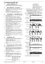
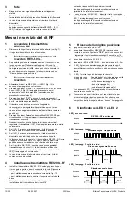
1.1.4 Control mode; DIP switches 1 and 2
DIP-switch 1 OFF and DIP-switch 2 OFF
Self learning
Adaptive control (standard) for all normal conditions
DIP-switch 1 OFF and DIP-switch 2 ON
PID 12
Normal controlled systems for situations with normal
temperature
variations
DIP-switch 1 ON and DIP-switch 2 OFF
PID 6
Fast controlled systems for situations with great
temperature
variations
DIP-switch 1 ON and DIP-switch 2 ON
2-Pt
Difficult controlled systems, proper on/off controller with a
switching differential of 0.5 °C
(also refer to Fig.
11/A
).
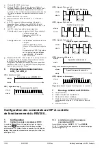
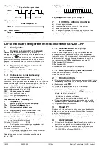
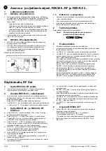
1.1.5 Periodic pump run DIP-switch 5
This function protects the pump against seizing during longer off
periods. Periodic pump run is activated for a minute every 24 hours
at 12:00 (when pump run is activated, the flame symbol
appears on the display). To store press the set button (also refer to
Fig.
11/D
).
DIP-switch 5 OFF (Standard)
DIP-switch 5 ON
Only useable with controled cirulating pumps.
1.1.6 Heating / cooling mode DIP-switch 4
DIP-switch 4 OFF (Standard) for heating
DIP-switch 4 ON for cooling
(also refer to Fig.
11/C
)
2 Functional
check
a) Check the display. If there is no display, check the correct fitting
and function of the batteries.
b) Operating
mode .
c) In the case of heating mode, set the set value temperature to
29 °C .
d) The relay and thus the regulating unit must respond after no
more than 1 minute the symbol
appears on the display. If
this is not the case:
•
Check regulating unit and wiring
•
Room temperature may be higher than 29 °C.
e) Reset set value temperature
to its previous level (heating
mode 19 °C,or your individual temperature).
3 Reset
User-defined data:
Press the button behind the pin opening for at least one second:
this resets the user-specific settings to their default values. The
clock starts at 12:00. During the reset time, all sections of the
display light up, enabling them to be checked.
4 Notes
•
The controler conforms to “Software Class A” and is for use in
“normal” pollution situation
•
REV200…RF/SET is a set of units consisting of electric room
temperature controller/thermostat with a weekly timeswitch and
transmitter (REV200…RF) and a RF receiver (REV-R.03…)
8/30
09.02.2007
G2214xx
Building Technologies / HVAC Products