34 / 143
Siemens
Web Server OZW672... V6.0
CE1C5712en
Building Technologies
Commissioning
2015-10-13
2.5.4.6 Energy
indicator
The menu "Energy indicator" is displayed if the controller is connected to the Web
Server that supports the Energy indicator. The menu is hidden if no devices of this
type are connected.
2 e-mail receivers can be defined for the Energy indicator. Settings are made at:
Path: Home > 0.5 OZW672... > Settings > Energy indicator
The descriptions are available in Section 6.5, E-mail with "Energy indicator" for the
plant
Visibility of the "Energy indicator" can be defined:
Path: Home > 0.5 OZW672... > Settings > Energy indicator
The description is available in Section 6.2.5, "Energy indicator" visibility.
2.5.4.7 Trend
2 e-mail receivers can be defined for the trend function. Each of the 4 trend
channels can send its information at a defined interval to one or both e-mail
receivers. Set at:
Path: Home > 0.5 OZW672... > Settings > Trend
Descriptions are available in Section 8.3, Send Trend data by e-mail.
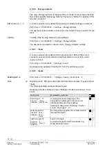
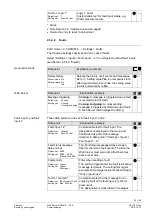
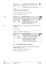
2.5.4.8 Inputs
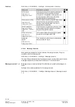
Path: Home > 0.5 OZW672… > Settings > Inputs > Fault input 1…2
Digital inputs D1, D2 help connect potential-free status contacts. They act as fault
inputs.
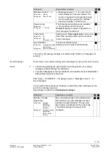
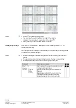
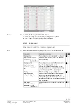
The following settings configure the fault inputs.
Response to faults is defined in menu "Settings > Faults (see Section 2.5.4.9,
Faults.
Data point
Explanation, example
Fault input 1…2*
Default val: (Blank)
Setting val: Max. 20 char.
Customizable text for fault input. The
designation is displayed in the menu and
transmitted as part of the message.
Identical to data point in "Settings > Faults >
Local > Fault input 1…2".
—
Normal position
Default val: Open
Setting val: Open,
Closed
Normal position specifies the contact position
deemed "No fault".
—
Text for: Logic 0*
Default val: 0
Setting val: Max. 20
characters
Logic 0: No fault.
Customizable text for fault input status, e.g.
Water pressure normal.
—
E-Mail receiver 1…2
Visibility
Fault input 1...2
Note

