background image

22 / 44

Siemens

VAV compact controller KNX/PL-Link G..B181.1E/KN

CE1P3547en

Building Technologies

2017-03-23

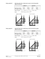
The following formula can be used to calculate the maximum cable lengths.

Operating voltage

Permissible voltage
drop per line

Formula for cable
length

AC 24 V

4 % of AC 24 V

L =

P

A

1313

Ζ

m

A  Cross-sectional area in [mm

2

]

L  Permissible cable length in [m]
P  Power consumption in [VA] or [W];
 

refer to the actuator’s type field

Operating
voltage

Power
consumption

Perm. voltage drop for line...
1 (G), 2 (G0)

AC 24 V

3 VA

4 % of AC 24 V

Determine the cable lengths for 4 actuators operating on AC 24 V. Decisive for
sizing the cable are only the AC currents on lines 1 (G) and 2 (G0). Maximum
permissible voltage drop =

4 % per line

.

  Consumption = 4 x 3 VA = 12 VA

  Line current = 4 x 0.125 A = 0.5 A

Permissible single cable length for G and G0:

  164 m with a cross-sectional area of 1.5 mm

2

  274 m with a cross-sectional area of 2.5 mm

2

4.2.2  Bus 

cabling

Instructions regarding topology and addressing in KNX networks can be found in
the documents [13] and [16]. The following sections presuppose electrical
installations that conform to the KNX-TP1 standard

Formula for cable
length

Example:

Power

consumption and
permissible voltage drop
(1 VAV controller)

Example:

Parallel

connection of
4 actuators

Содержание OpenAir G..B181.1E/KN Series

Страница 1: ...s OpenAirTM VAV compact controller KNX PL Link G B181 1E KN Technical Basics CE1P3547en 2017 03 23 Building Technologies ...

Страница 2: ...17 03 23 Issued by Siemens Switzerland Ltd Building Technologies Division International Headquarters Gubelstrasse 22 6301 Zug Switzerland Tel 41 41 724 24 24 www siemens com buildingtechnologies Siemens Switzerland Ltd 2017 Technical specifications and availability subject to change without notice ...

Страница 3: ...nciple 15 3 Functionality application 16 3 1 Fields of application 16 3 2 Equipment combinations 16 3 3 Application examples 17 3 3 1 Application example 1 Supply air control 17 3 3 2 Application example 2 Supply and extract air control 17 3 3 3 Application example 3 AHU optimization 18 3 4 Further application examples 19 3 4 1 Application examples for Synco 700 Series C or newer 19 3 4 2 Applicat...

Страница 4: ...ngineering 34 6 3 Commissioning 35 6 3 1 Preconditions 35 6 3 2 KNX S mode commissioning 36 6 3 3 KNX LTE mode commissioning 36 6 3 4 PL Link commissioning 36 7 Safety and EMC optimization 37 7 1 Safety notes 37 7 2 Device specific regulations 38 7 3 Notes on EMC optimization 39 8 Technical data 40 9 Parameters and datapoints 41 9 1 Parameter description 41 9 2 Device parameters ACS931 ACS941 AST2...

Страница 5: ...s of all documents are checked at regular intervals Any corrections necessary are included in subsequent versions Documents are automatically amended as a consequence of modifications and corrections to the products described Please make sure that you are aware of the latest document revision date If you find lack of clarity while using this document or if you have any criticisms or suggestions pl...

Страница 6: ...he networked VAV compact controllers GDB181 1E KN and GLB181 1E KN These devices are designed for controlling variable or constant air volume flows This document is structured along the according workflow Following a description of the devices and their application mounting engineering and commissioning are covered A references section lists technical data parameters and data points 1 4 Abbreviati...

Страница 7: ...ftware for OEM N5853 6 ACS941 PC Software for Service N5854 7 Scan to HIT App for iOS devices link 8 Scan to HIT App for Android devices link 9 Desigo V5 Basic manual chapter 21 Room automation 10 Desigo XWP ABT Online help 11 Desigo TRA Setup and Service Assistant SSA CM111050en 12 Desigo TRA mounting and installation manual CM111043en 13 Synco Communication over KNX Bus Basic documentation P3127...

Страница 8: ...nd actuator parameters and supports access levels for service technicians and OEMs Datasheet A6V10631836 ACS941 AST11 The PC software for service ACS941 can be used for setting and reading a certain set of device parameters values set by OEM and current configuration and actual values cf section 9 2 For connecting to a PC with RS232 interface an interface converter AST11 is required Datasheet N585...

Страница 9: ... to Hit App can be used to retrieve technical information about the actuator by scanning the DMC data matrix code in the top right corner of the actuator The app can be obtained free of charge at 7 resp 8 For information regarding accessories and spare parts for VAV compact controllers please refer to datasheet N4698 Accessories ...

Страница 10: ...or GMA131 1E 7 Nm GCA131 1E 18 Nm ASV181 1E 3 with 3P actuator GMA136 1E 7 Nm GCA136 1E 18 Nm ASV181 1E 3 with 3P actuator GEB136 1E 15 Nm GBB136 1E 25 Nm GLB136 1E 35 Nm ASV181 1E 3 with 3P actuator GEB131 1E 15 Nm GBB131 1E 25 Nm GLB131 1E 35 Nm Bus connection Actuator 10 Nm and 5 Nm Actuator 5 Nm Yes No No No Yes Yes No No Yes Yes Auxiliary switch No Yes Modbus No GDB181 1E BA 5 Nm BACnet GDB18...

Страница 11: ...upported for backward compatibility reasons Version Series E Series F Series G Production period 10 2011 03 2014 03 2014 01 2017 01 2017 FW version 4 16 4 18 4 24 ETS profile v1 x supported supported supported ETS profile v2 x not supported not supported supported Version identification Version Series E Series F Series G Identification Features Communication over Desigo PL Link or KNX LTE and S mo...

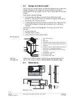
Страница 12: ...n Components contained in the housing Note the housing cover must not be removed Controller electronics differential pressure sensor synchronous motor for the damper actuator 1 Shaft attachment screw 2 LED 3 Push button 4 Configuration and maintenance interface below cover 5 Connection nozzle for measuring differential pressure in the VAV box 6 Connection nozzle for measuring differential pressure...

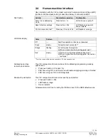
Страница 13: ...nection test successful 1 Orange flashing a Factory reset in progress b When a connection test was triggered wait 1 Red steady c Device is in programming addressing mode d When a connection test was triggered Connection test failed 2 1 Function or part of the function available in PL Link operation only The VAV compact controllers can be set into addressing programming mode by push button ƒ Press ...

Страница 14: ...tations regarding cable length power supply number of attachable devices and distances apply For more details please refer to 13 and 16 or to the KNX standard N1 G B181 1E KN N2 RDG400KN Example for a VAV enabled room unit Terminal layout may differ for each device Devices with twin terminals or internally connected terminals may be encountered as well as bus connection in junction boxes Please re...

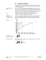
Страница 15: ... purposes The differential pressure sensor operates long term stable and without recalibration In critical cases material compatibility tests should be made while giving consideration to harmful substances and concentrations The VAV box manufacturer OEM uses the parameter Vn to adjust the operating range of the differential pressure sensor 0 300 Pa to the actual VAV box nominal pressure Χpnat the ...

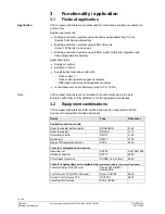
Страница 16: ...a nominal torque of up to 5 or 10 Nm VAV compact controllers are not suitable for environments where the air is saturated with sticky or fatty particles or contain aggressive substances 3 2 Equipment combinations VAV compact controllers are KNX certified and may be connected to all KNX devices with compatible S mode data points Device Type Data sheet Controllers and room units Room thermostat with...

Страница 17: ...re control cooling or heating with one VAV compact controller The building user sets a temperature setpoint in C which is converted by a VAV capable KNX thermostat e g RDG400KN into a 0 100 setpoint for the air volume flow taking into account the air volume flow temperature as delivered by the AHU 3 3 2 Application example 2 Supply and extract air control If one VAV compact controller is used for ...

Страница 18: ... below or in Desigo PL Link environments The control of variable speed drives VSDs can be accomplished by various means Below depicted is DC 0 10 V control but plants with USS or Modbus controlled VSDs are also possible depending on the connector layout of the universal primary controller For a detailed explanation of this application in a Synco 700 system please refer to 14 chapter 23 For a detai...

Страница 19: ...ndividual Rooms Preferred controller Range select RDG RDF in dropdown list and Operating voltage AC 24 V In the bottom area matching application examples appear User interface is subject to changes 3 4 1 2 Application examples in printed documents Application examples in printed documents can be found in RDG RDF Application Guide 0 92173 DE EN Basic Documentation RDF341 P3172 Basic Documentation R...

Страница 20: ...dity must be observed The actuator may only be manually operated when separated from power supply If required the angular rotation can be set by appropriate adjustment of the adjusting screw Connection of PC tool ACS931 ACS941 to G B181 1E KN 1 PC with ACS931 or ACS941 2 G B181 1E KN 3 Strain release strip Connection of handheld tool AST20 to G B181 1E KN 1 AST20 2 G B181 1E KN 1 2 3 AST11 Mountin...

Страница 21: ...are to be sized depending on the type of actuator used and based on the following data Type Operating voltage Line Max permissible voltage drop GDB181 GLB181 AC 24 V G0 G each 4 tot 8 The power supply voltage drop at AC 24 V must not exceed 8 4 over the G0 The chart below applies to AC 24 V operating voltage and shows the permissible cable length L as a function of power P and the cross sectional ...

Страница 22: ... the cable lengths for 4 actuators operating on AC 24 V Decisive for sizing the cable are only the AC currents on lines 1 G and 2 G0 Maximum permissible voltage drop 4 per line Consumption 4 x 3 VA 12 VA Line current 4 x 0 125 A 0 5 A Permissible single cable length for G and G0 164 m with a cross sectional area of 1 5 mm 2 274 m with a cross sectional area of 2 5 mm 2 4 2 2 Bus cabling Instructio...

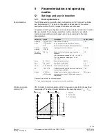
Страница 23: ...OS setpoint commands damper position VAV Opening direction CW R CCW L Opening direction of air damper CW R Adaptive positioning Off On Adaption of actual opening range to position feedback Off No adaption mapping 0 90 0 100 On Pos adaption mapping e g 0 60 0 100 Off Vmax 20 120 Maximum air volume flow 100 Vmin 20 100 Minimum air volume flow 0 Vnom 0 60 000 m 3 h Nominal air volume flow 2 100 m 3 h...

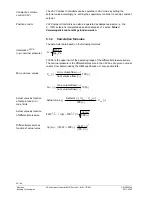
Страница 24: ... 300 Pa is the upper limit of the operating range of the differential pressure sensor The nominal pressure is the differential pressure in the VAV box at a given nominal volume flow determined by the OEM specification cf also section 2 6 Ζ Ζ Ζ Ζ h 3 m h 3 m 100 flow volume nom flow volume min Vmin Ζ Ζ Ζ Ζ h 3 m h 3 m 100 flow volume nom flow volume max Vmax Ζ Ζ Ζ Ζ Ζ V 100 V V Setpoint value Actua...

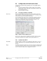
Страница 25: ...are ACS941 allows to set or to display the parameters as listed in section 5 1 The software supports trend functions and allows comparing the values set by the OEM with the values currently stored in the device Thus changes by parties other than the OEM can be detected Figure 1 ACS941 with VAV configuration pane Next to the PC software ACS941 an OEM version ACS931 5 with extended functionality is ...

Страница 26: ...ler master V Volume flow of supply air controller Master slave V Volume flow of extract air controller Slave 5 3 2 Min max control by the supervisory controller When setting the minimum maximum air volume flow in the supervisory controller the VAV compact controller has to be configured with min V 0 and max V 100 VAV ratio control 1 1 Supply air Extract air min V max V min V max V Supervisory cont...

Страница 27: ...air 35 Yextract_air Ysupply_air 20 15 Result Vsupply_air 35 Vextract_air 15 min V max V V min V max V V supply_ air V r extract_ ai V VAV ratio control 20 constant excess extract air volume flow negative pressure in the room Supply air Extract air min V max V min V max V Supervisory controller 20 80 40 100 VAV compact controller 0 100 0 100 Reference signal Ysupply_air 35 Yextract_air Ysupply_air ...

Страница 28: ... With this setting the supervisory controller reference signal for both the supply air and extract air controller is the same Thus supply air extract air control with a single reference signal is possible VAV ratio control 1 1 Supply air Extract air min V max V min V max V Supervisory controller 0 100 0 100 VAV compact controller 20 80 20 80 Reference signal Ysupply_air Yextract_air 25 Result Vsup...

Страница 29: ... V supply_ air V r extract_ ai V VAV ratio control 20 constant excess extract air volume flow negative pressure in the room Supply air Extract air min V max V min V max V Supervisory controller 0 100 0 100 VAV compact controller 20 80 40 100 Reference signal Ysupply_air Yextract_air 25 Result Vsupply_air 35 Vsupply_air 55 100 min V max V 100 80 60 40 20 20 0 40 60 80 0 100 60 40 120 Reference sign...

Страница 30: ...perating mode is required In this mode the actual value signal of the master controller supply air is the reference signal for the slave controller extract air cf also section 6 2 2 VAV ratio control 1 1 Supply air Master Extract air Slave min V max V min V max V Supervisory controller 0 100 0 100 VAV compact controller 20 80 0 100 Reference signal Ymaster 25 Result Vmaster Vslave 35 min V max V V...

Страница 31: ...V compact controller 20 80 20 80 Reference signal Ymaster 25 Result Vmaster 35 Vslave 15 min V max V V min V max V V master V slave V VAV ratio control 20 constant excess extract air volume flow negative pressure in the room Supply air Master Extract air Slave min V max V min V max V Supervisory controller 0 100 0 100 VAV compact controller 20 80 20 120 Reference signal Ymaster 25 Result Vmaster 3...

Страница 32: ...us load is only 5 mA Desigo PL Link systems do not support the use of line couplers 6 1 2 Documentation of engineering and commissioning It is highly recommended to document all planning data and settings in a way that is easily accessible after a long interval Especially if special calculated parameters or plant specific adaptations had to be made during engineering and commissioning these should...

Страница 33: ...ted the installed devices are found when the ACS790 device list is refreshed In the device list the collected IDs can be used to identify the devices and to assign physical addresses according to the intended plant topology With this approach commissioning can be done without much effort For an alternative commissioning procedure cf section 6 3 3 Plants with supply air and extract air control in K...

Страница 34: ...ution center The OEM manufactures the VAV boxes and adjusts the VAV compact controllers mainly by setting the parameter Vn cf section 2 6 The preconfigured VAV boxes are then delivered to the construction or renovation site 3 The electrical installer EI mounts the VAV boxes and removes the address labels He attaches them to a building plan or something comparable This building plan is then forward...

Страница 35: ...ates State intended behavior User action Device response LED Functionality available in all system environments Power up device starts up Connect device to power supply LED is orange goes off after power up is completed Faultless operation none LED is off Set device to programming addressing mode Short key press 0 5 s LED is red no time limit Reset device to factory settings Long key press 20 s LE...

Страница 36: ...s red 2 In ACS790 click button Programming mode Address assignment enter physical address click Write Enter a physical address and short description for the selected VAV compact controller Click Write to close dialog box Repeat steps for all VAV compact controllers for commissioning Continue Further configuration with ACS790 6 3 4 PL Link commissioning Multiple VAV compact controllers can be conne...

Страница 37: ... charge Third party regulations issued by general contractors or building operators The electrical safety of building automation and control systems supplied by Siemens depends primarily on the use of extra low voltage with safe isolation from mains voltage Depending on the type of extra low voltage earthing a distinction is to be made between SELV and PELV as per HD 384 Electrical plants in build...

Страница 38: ... unfavorable 20 Fusing of AC 24 V operating voltage Secondary side of transformer According to the effective load of all connected devices Line G system potential must always be fused Where required line G0 system neutral also 7 2 Device specific regulations Among other aspects the safety of devices is ensured by extra low voltage power supply AC 24 V as per SELV or PELV Electrical parallel connec...

Страница 39: ... cables from other cables by a minimum of 150 mm or route in separate ducting Cross high interference cables with equipment susceptible to interference only at right angles If in exceptional cases signal and interference emitting power cables are run in parallel the risk of interference is high In that case limit the cable length of the DC 0 10 V positioning signal line for modulating actuators In...

Страница 40: ...ype 1 Electromagnetic compatibility Application For residential commercial and industrial environments GDB181 1E KN GLB181 1E KN EU Conformity CE A5W00003842 1 A5W00000176 1 GDB181 1E KN GLB181 1E KN RCM Conformity A5W00003843 1 A5W00000177 1 Environmental compatibility The product environmental declaration CM2E4634E 1 contains data on environmentally compatible product design and assessments RoHS...

Страница 41: ... during start up The actual range e g 15 75 is then mapped to the 0 100 positioning signal If set to Off 0 100 is interpreted as 0 90 Backup mode Backup position If no setpoint has been received for the time interval defined by the parameter Backup timeout the actuator can assume a predefined behavior When Backup mode is enabled the damper drives to the defined Backup position or keeps the last kn...

Страница 42: ...ing tools ETS ETS3 or ETS4 0 6 or newer ACS ACS790 version 8 00 or newer Designation Setting Factory setting Can be set with Nominal volume flow 0 214 000 m 3 h 100 m 3 h ETS ACS ABT Hysteresis volume flow 1 214 000 m 3 h 1 m 3 h ETS ACS ABT Min repetition time volume flow 10 s 900 s 10 s ETS ACS ABT Minimum volume flow 20 100 0 ETS ACS ABT Maximum volume flow 20 120 100 ETS ACS ABT Elevation abov...

Страница 43: ...mit 1 1 0 1 0 1 005 _Alarm 1 bit 0 No alarm 1 Alarm 9 Overridden Transmit 1 1 0 1 0 1 002 _Bool 1 bit 0 False 1 True 10 Override position 1 Receive 1 1 1 0 1 1 003 _Enable 1 bit 0 Disable 1 Enable 11 Override position 2 Receive 1 1 1 0 1 1 003 _Enable 1 bit 0 Disable 1 Enable 12 Balancing mode Receive 1 1 1 0 0 1 003 _Enable 1 bit 0 Disable 1 Enable 13 Vmin 5 Receive 1 1 1 0 1 8 010 _Percent_V16 2...

Страница 44: ...patible manner and in accordance with the latest developments in environmental recycling and disposal techniques Local and currently valid legislation must be observed The aim is to achieve maximum recyclability of the basic materials while ensuring minimum strain on the environment To do this note the various material and disposal notes printed on specific components The Environmental Declaration...

Отзывы: