


Hardware Installation
19
Building Technologies
048_DMS_NK8237_ICC_MP4.40_A6V10316241_a_en.doc
Fire Safety & Security Products
06.2011
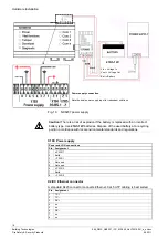
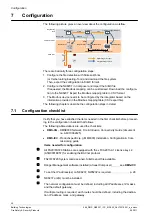
X101: Onboard I/O (output relay)
Pin Assignment
1 Common
2 NO
output
3 NC
output
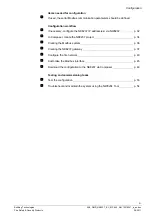
X102: Onboard I/O (inputs)
Pin Assignment
1
Input 1 (Mains failure)
2
Input 2 (Battery fault)
3
Input 3 (Power supply fault)
4 Common
5 +
Val
6 -
Val
COM 1, COM 2: RS232 connectors
RS232 lines are connected to 9pin D-Sub connectors, female type
Pin Assignment
COM
1-2
1 CD
2 RXD
3 TXD
4 DTR
5 GND
6 DSR
7 RTS
8 CTS
9 RI
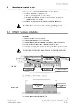
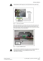
DIN Rail installation
The modules are supplied in a plastic box that can be easily attached to the DIN
rail by hooking it on the top of the rail and pressing it in on the opposite side. To
detach the box, pull downward on the tab located at the rear of the module. The I/O
modules are mounted the same way.
i
Before removing the box, carefully disconnect the flat cable (bus) of the I
2
C mod-
ule, as well as the power supply cables.
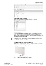
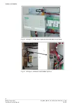
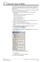
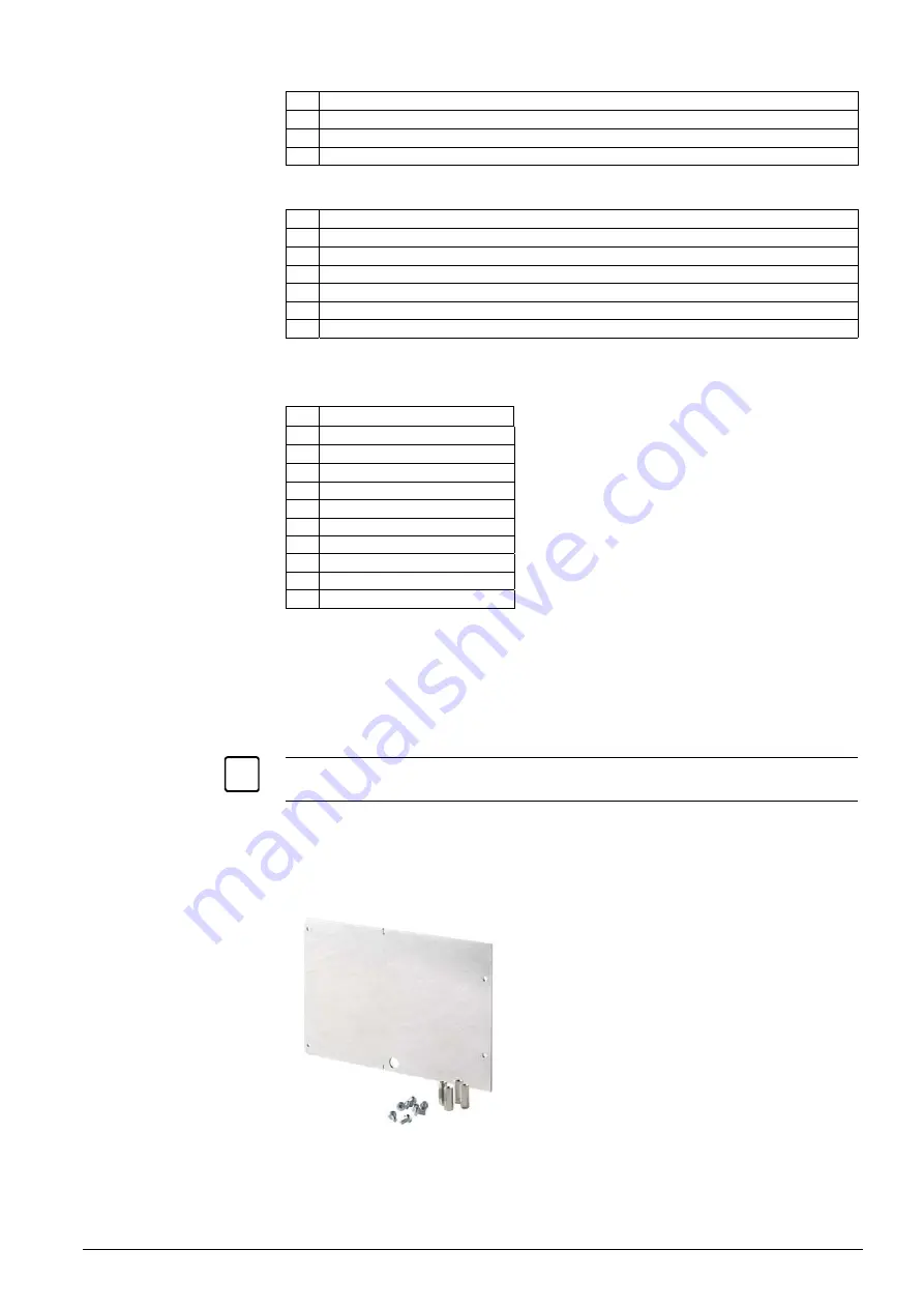
Installation in subsystem housing without DIN-rail
NK8237 can be installed without the plastic box into the control unit cabinet. In this
case, the NKA8011-A1 mounting plate may be needed.
Fig. 11 NKA8011-A1 mounting plate for NK8237