6
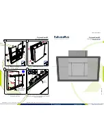
To meet these requirements, two wire ducts are
mounted along the sides of the rack assembly, as
shown in Figure 8. Remove the wire duct cover,
route all non-power limited wiring through the
ducts, then snap the cover back in place.
Refer to the Installation and Power Limited Wiring
Instructions for the MME-3 Backbox, P/N 315-
094883, for further information on power and
non-power limited wiring.
NOTE: If power-limited wiring is not used within a
rack mount system, then the following
guidelines do not apply. In that case, be
sure to follow standard wiring practices.
4
E
L
B
A
T
T
I
K
K
R
-
S
E
L
B
A
C
)
4
4
0
3
9
8
-
0
0
5
N
/
P
(
E
L
B
A
C
E
P
Y
T
F
O
E
P
Y
T
M
E
T
S
Y
S
S
E
C
A
L
P
E
R
S
D
N
E
T
X
E
R
O
S
T
C
E
N
N
O
C
S
E
L
U
D
O
M
E
L
B
A
C
H
T
G
N
E
L
n
o
b
b
i
R
r
o
t
c
u
d
n
o
C
4
1
V
L
X
M
s
e
c
a
l
p
e
R
1
P
,
1
-
M
C
A
o
t
3
P
,
1
-
M
M
T
"
4
2
n
o
b
b
i
R
r
o
t
c
u
d
n
o
C
5
1
V
L
X
M
s
e
c
a
l
p
e
R
4
P
,
1
-
M
C
A
o
t
P
,
1
-
N
N
A
1
"
4
2
V
L
X
M
s
e
c
a
l
p
e
R
8
P
,
2
-
B
M
M
o
t
P
,
1
-
M
C
A
5
n
o
b
b
i
R
r
o
t
c
u
d
n
o
C
5
1
r
o
"
0
4
L
X
M
s
e
c
a
l
p
e
R
8
P
,
2
-
B
M
M
o
t
P
,
1
-
N
N
A
1
y
r
e
tt
a
B
e
ri
W
2
V
L
X
M
/
L
X
M
s
e
c
a
l
p
e
R
2
P
,
2
/
1
-
B
M
M
o
t
y
r
e
tt
a
B
"
0
6
e
l
b
a
C
e
ri
W
9
V
L
X
M
s
d
n
e
t
x
E
1
-
M
M
M
o
t
7
P
,
1
-
M
C
A
"
6


