Siemens IONPURE VNX50HH-2 Скачать руководство пользователя страница 7

IONPURE 

®


VNX50HH-2 CEDI Modules


Page 7


IP-MAN-VNX50HH2


  Do not operate the module under conditions other than those stated in the module manual.  The 

prescribed feed water and electrical requirements, and flow configurations, must be followed at all 
times.  If the feed water quality or the product water requirements change, contact the 

IONPURE


Technical Support department for assistance. 

Once every six months: 

  Make sure all wiring connections are tight 

  Test safety interlocks such as flow switches or connections to upstream equipment 


1.5.  Shutdown Precautions 


  Confirm that the pressure in the unit is relieved until all pressures inside the unit are atmospheric.  

(i.e., all pressure gauges should read zero).   

  Drain standing water and plug all inlets and outlets. 


2.  PRE-INSTALLATION: PREPARATION & REQUIREMENTS 

This section contains the following pre-installation information: 


Tools and equipment 

- Tools and equipment needed to install the module


Module Inspection 

-


Inspecting the VNX module for damage


Operating conditions 

-


Temperature range, space requirements, electrical connections, feed water 

specifications, plumbing and drain requirements


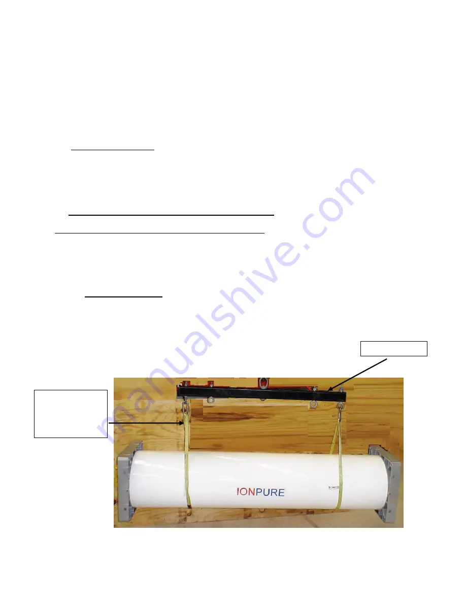
2.1.  Tools and Equipment 

 
The following items are required to unpack, position, and install the VNX module: 

  Spreader bar mechanism to move the module into place  

  Slip joint pliers   

 Wire 

cutters/strippers 

  Phillips head screwdriver 


Spreader bar 

Strapping rated 

for at least 

1000 lbs (454 

kg) 

Содержание IONPURE VNX50HH-2

Страница 1: ...IONPURE VNX50HH 2 CEDI Modules Operation Maintenance Manual IP MAN VNX50HH2 June 2009 Manual Covers Part IP VNX50HH 2 10 Technology Drive Lowell Massachusetts 01851 Tel 866 876 3340 Fax 978 934 9499 ...

Страница 2: ...ALLATION PREPARATION REQUIREMENTS 7 2 1 Tools and Equipment 7 2 2 Electrical and Plumbing Connections 8 2 3 Inspect the Module 10 2 4 Operating Requirements 10 2 5 Flow Rates and pressure drops 11 3 VNX MODULE INSTALLATION AND OPERATION 12 3 1 Moving the VNX Module into Place 12 3 2 Water Connection Configuration and Fittings 12 3 3 Electrical Connections 15 4 DETERMINE OPERATING DC CURRENT PRIOR ...

Страница 3: ...ical Sanitization Procedures 21 6 8 Cleaning with 2 0 Hydrochloric Acid HCl 22 6 9 Cleaning with 5 Brine 1 Caustic Solution 24 6 10 Cleaning or Sanitizing with Sodium Percarbonate 25 6 11 Sanitizing with Peracetic Acid 27 7 TROUBLESHOOTING 31 8 SHUTDOWN AND STORAGE 38 8 1 SYSTEM SHUTDOWN 38 8 2 STARTUP AFTER SHUTDOWN 38 APPENDIX A VNX50HH 2 MODULE SPECIFICATIONS 39 APPENDIX B VNX50HH LAYOUT ELEVAT...

Страница 4: ... is altered or section items are omitted during a reproduction in whole or in part and instructions or definitions within the reproduction result in personal injury to those who follow the altered instructions the burden of responsibility for personal injury falls solely on the party who effects the reproduction MANUAL USER S GUIDE This manual describes the procedures necessary to install operate ...

Страница 5: ...dules are designed to be installed in either single or multiple Continuous Deionization VNX systems Their compact state of the art design assures ease of installation maintenance and service Compared to the VNX50 2 the VNX5HH 2 module was designed for higher feed water hardness tolerance They are differentiated by a green HH marking on the vessel of the VNX50HH 2 module VNX50HH 2 modules are avail...

Страница 6: ...ES To eliminate the possibility of electric shock confirm that all GROUND WIRES ARE PROPERLY CONNECTED Thoroughly read all the information in this manual before operating the VNX model modules THE MODULE MUST BE OPERATED ACCORDING TO THE DESIGN SPECIFICATIONS FOR TEMPERATURE AND HUMIDITY IMPORTANT Pipe sections prepared for installation must be inspected and be free of debris from storage or cutti...

Страница 7: ...ed until all pressures inside the unit are atmospheric i e all pressure gauges should read zero Drain standing water and plug all inlets and outlets 2 PRE INSTALLATION PREPARATION REQUIREMENTS This section contains the following pre installation information Tools and equipment Tools and equipment needed to install the module Module Inspection Inspecting the VNX module for damage Operating conditio...

Страница 8: ...ction box follows DC wire color conventions Red Black Figure 2 1 Junction Box End of Module Inlet and Outlet plumbing connections Ionpure VNX50HH 2 modules have molded PPO end blocks with FEMALE connections There are four 4 necessary custom ACME thread connection points for more information see Connection Drawings in Appendix B Product Inlet Dilute Feed Product Outlet Product Reject Inlet Concentr...

Страница 9: ...C 1 1 2 Female Socket PP 50mm Butt Weld PVDF 50mm Butt Weld Grounding of the module piping DILUTE IN DILUTE OUT FI PI C PI RO Permeate CEDI Reject PI FI CEDI Product CONC IN CONC OUT PI Figure 2 2 Depicts the flow diagram for the VNX HH Note Product water Dilute out feeds the Concentrate Inlet To avoid the risk of electrical shock some form of grounding must be used on any stream where the plumbin...

Страница 10: ...The VNX module requires indoor installation out of direct sunlight The maximum ambient room temperature should not exceed 113 F 45 C The module can tolerate humidity of up to 90 as long as condensation does not occur Space Requirements The physical dimensions of the VNX Module are given in appendix A In addition to the size of the module itself the arrangement of the piping and electrical connecti...

Страница 11: ...O permeate Feed water conductivity equivalent including CO2 40 µS cm Silica SiO2 1 ppm Iron Manganese Sulfide 0 01 ppm Total chlorine 0 02 ppm as Cl2 Total Hardness 2 0 ppm as CaCO3 Dissolved organics TOC 0 5 ppm Operating pH range 4 11 Operating Temperature 40 113 F 5 45 C Inlet pressure 100 psi 7 bar Note Recycling the VNX reject to the RO feed will cause the CO2 load on the VNX to increase and ...

Страница 12: ...eam pretreatment equipment and piping have been thoroughly flushed with particle free water before connecting them to the VNX Module Flushing removes any particles left in the piping from cutting and assembly If particles remain they could plug the passages inside the VNX Module NOTE Failure to properly flush the pretreatment water system of installation debris to drain prior to flowing water to t...

Страница 13: ...tional module specific connection information see appendix B The unit comes with 4 factory installed PVC connection adapters The unit comes with 4 factory installed PVC plugs There are several important points regarding the piping connections Sealing Mechanism The seal is created by a dual o ring between the smooth hole wall of the end block and the connection adapter This is similar to an RO end ...

Страница 14: ...ction Adapter PVC Piping Adapter Material To avoid corrosion the piping adapters and plugs must be non metallic Factory supplied plugs and adapters are made of PVC Additional high purity adapter kits are available if required for installation See Appendix C for the Polypropylene plug adapter drawings Tightening Adapters should be tightened to ensure that orings are engaged in the endplate The maxi...

Страница 15: ...lying DC power Operation with polarity reversed will permanently damage the cathode It is critical that the red and black wires are correctly oriented on the positive and negative terminal blocks Do not run AC and DC wiring within the same conduit This may cause interference and lead to malfunctions Disconnect power before opening any enclosure and follow accepted Lockout Tag out procedures when w...

Страница 16: ...e RO interlock if applicable Test pressure relief if applicable Set alarm points 5 2 Notes on Recovery Silica and Hardness VNX50HH 2 VNX recovery of 90 is limited to systems with feed water total hardness of less than 1 ppm as CaCO3 For systems operating with CEDI feed water hardness from 1 2 ppm as CaCO3 the maximum water recovery is limited to 80 In addition there is a minimum reject flow of 2 6...

Страница 17: ...justed to ensure that the module is operating with the correct recovery and adjusted to ensure that the product outlet pressure is about 2 10 psig higher than the reject outlet pressure at the desired flow rates See Example Pressure Scenario Below 25 PSIG 50 PSIG 25 PSIG Outlet Adjust the DC power supply to the current setting of 8 amps See Section 4 for more details Test all flow switches and int...

Страница 18: ...t the end of the troubleshooting in Section 7 Because instrumentation may vary depending on the type of system the module is installed into this log sheet may not apply to your particular system The system manual should contain log sheets more appropriate for your particular system However the items in bold must be filled out to maintain module warranty Periodic Maintenance Perform the following t...

Страница 19: ...ing and other equipment before cleaning or sanitization to remove debris that might damage the system During cleaning the following equipment is required Tank Connect a tank to the VNX system The tank should be large enough to accommodate solution volumes as shown in this section The cleaning solution will be prepared in this tank Pump Install a cleaning pump between the system and the cleaning ta...

Страница 20: ... and hose are compatible with the cleaning solutions 6 6 System Preparation for Cleaning or Sanitization NOTE The following cleaning procedures are based on the piping setup shown in Figure 6 1 If your piping setup is different you may need to alter these procedures Turn off the DC power supply Close the following valves to the VNX system o Feed Valve o Product Valve Connect the discharge of the c...

Страница 21: ...re adding chemicals to tank Flush all hoses and tank with clean water BEFORE adding chemicals To reduce the possibility of chemical sprays relieve the pressure in chemical lines before disassembly Follow the manufacturer s chemical safety instructions on the container labels Check the pH level in any solution before letting it flow to the drain Follow all discharge limitations Do not run a cleanin...

Страница 22: ...th a final 5 sodium chloride flush see Service Bulletin 2007 02 Extended soaking or increasing the acid concentration in the range from 2 4 HCl based on the severity of electrical stack resistance increase increases the benefits of this treatment NOTE If you are unsure whether the module is scaled or organically fouled clean first with brine then caustic clean followed by acid clean 6 8 Cleaning w...

Страница 23: ... add more HCl to maintain a pH of approximately 0 5 9 Turn off the cleaning pump 10 Check pH Neutralize if necessary Drain the tank STEP 2 Salt Flush To Drain This salt flush rinses the cleaning solution from the module and returns the ion exchange resin to the sodium and chloride forms Chemicals needed for Step 2 5 NaCl VNX50 HH Water RO permeate or CEDI product 180 gal 675 liters Sodium chloride...

Страница 24: ...moves organic foulants from the module Chemicals necessary for Step 1 VNX50 HH Water RO permeate or CEDI product 99 gal 375 liters Sodium chloride NaCl 42 lbs 18 75 kg Sodium hydroxide NaOH pellets OR 50 NaOH 8 25 lbs 375 kg 1 29 gal 4 8 liters NOTE The following cleaning procedures are based on the piping setup shown in Figure 6 1 1 Prepare the VNX system for chemical cleaning Follow the instruct...

Страница 25: ... chemicals Do not use powdered sodium percarbonate It may contain impurities that could harm the module Sodium percarbonate is a combination of sodium carbonate soda ash and hydrogen peroxide It is an effective biocide and it reduces organic fouling and plugging In addition it is an effective cleaner for removal of biofilms Flush the VNX module with a 5 Sodium Chloride NaCl solution both before an...

Страница 26: ...dule before cleaning solution is introduced Chemical necessary for Step 2 VNX50 HH Water RO permeate or CEDI product 180 gal 675 liters 1 Fill the tank with the required amount of water 2 Start the cleaning pump and flush to drain for about three minutes 3 Turn off the cleaning pump 4 Drain the tank STEP 3 Cleaning Solution Recirculation This 1 sodium percarbonate step removes organics and biofilm...

Страница 27: ...outlet lines from the cleaning tank and direct to drain 2 Fill the tank with the water 3 Dissolve the sodium chloride NaCl in the water 4 Start the cleaning pump and flush to drain for about three minutes 5 Turn off the cleaning pump 6 Drain the tank STEP 5 Water Flush to Drain This step flushes the cleaning solution out of the system and prepares the system for return to operation 1 Close the cle...

Страница 28: ...ection 6 5 to prepare the VNX system for cleaning or sanitization Make sure that the cleaning tank drain valve is closed 2 Fill the tank with the required amount of water 3 Dissolve required amount of sodium chloride NaCl in the tank water 4 Open the cleaning pump suction valve and bypass valve completely 5 Divert the product and reject to drain 6 Start the cleaning pump When chemicals are well mi...

Страница 29: ...d solution into the tank 5 Open the cleaning pump suction valve and bypass valve completely 6 Start the cleaning pump When chemicals are well mixed gradually open the cleaning pump discharge valve while closing the bypass valve to adjust the product and reject flow rates to the values given in Section 6 5 7 Recirculate the solution through the module for 30 minutes 8 Turn off the cleaning pump 9 A...

Страница 30: ...to operation 1 Close the cleaning pump discharge valve Keep product and reject lines directed to drain and disconnect the cleaning equipment from the module 2 Turn on the feed water supply to the system Slowly open the feed valve to allow RO product water to flow through the module to drain 3 After flushing all residual cleaning solutions from the system follow the initial start up procedures in S...

Страница 31: ...uring shipment movement or operation Contact Ionpure Technical support Module leaks Module is faulty Contact your Local Service Provider Plumbing leaks Module adapters are loose Tighten adapters check O rings Poor water quality with power ON to unit Operating current incorrectly set Measure feed conductivity and CO2 Recalculate current according to Section 4 and adjust as necessary Module is foule...

Страница 32: ...NE ppm as Cl2 FEED CARBON DIOXIDE ppm as CO2 FEED CONDUCTIVITY µmho cm PRODUCT RESISTIVITY Mohm cm DC VOLTAGE volts DC CURRENT amps MODULE RESISTANCE volts amps ohms PRODUCT FLOW gpm or m3 h REJECT FLOW gpm or m3 h DILUTE INLET PRESSURE psig or bar DILUTE OUTLET PRESSURE psig or bar PRODUCT DP Dilutein Diluteout psig or bar CONCENTRATE INLET PRESSURE psig or bar CONCENTRATE OUTLET PRESSURE psig or...

Страница 33: ...lean reduce CEDI feed hardness and or lower CEDI recovery Yes No No Yes Yes No Call you local service provider Troubleshooting Flow Chart Increase in DC Volts Page 1 of 1 START HERE Caustic clean reduce CEDI feed silica and or lower CEDI recovery Excess silica in CEDI reject Yes No Cleaning removed organics from resin review process design and operation Does NaCl NaOH cleaning help Yes No ...

Страница 34: ...ticulates or biofouling evaluate system design and operation CEDI resin damaged Call Technical Support Yes No No Yes Yes Yes No Call your local service providor Troubleshooting Flow Chart Low CEDI Product or Reject Flow Page 1 of 1 Product flowmeter incorrect Recalibrate or replace flow meter Yes No START HERE Compare product pressure drop when circulating 5 NaCl solution as opposed to 1 NaOH solu...

Страница 35: ... Product Water Quality Page 1 of 3 CEDI feed TDS changed Adjust DC amperage Up for higher TDS Down for lower TDS START HERE Check IP Pro is desired quality possible Yes Yes No No Check IP Pro is desired quality possible Adjust DC amperage up for higher CO2 down for lower CO2 Yes Yes Increase pH ahead of RO to remove CO2 contact Tech Support or lower CEDI prod flow No No No Clean or replace RO memb...

Страница 36: ...g chart for DC volts Yes No Go to Next Flowchart Product flow increased Yes Troubleshooting Flow Chart Low CEDI Product Water Quality Page 2 of 3 Continued from previous flowchart Increase DC amperage Check IP Pro is desired quality possible Yes No No Is reject out psi product out psi No Adjust product out to 2 5 psi reject out Yes Go to chart for DC Volts ...

Страница 37: ...flow decreased Troubleshooting Flow Chart Low CEDI Product Water Quality Page 3 of 3 Continued from Previous Flowchart No Yes Contact Ionpure Technical Support www ionpure com Did cleaning restore quality No Removed particulates and or biofilm review process design operation Yes Also removed organics from resin review process design operation Yes No Check feed water Cl2 Check sanitization procedur...

Страница 38: ...er left stagnant within each module and the overall system 8 1 SYSTEM SHUTDOWN Shut off feed water to VNX module s Drain standing water out of VNX module s Close isolation valves to prevent evaporation of water in membranes and resins 8 2 STARTUP AFTER SHUTDOWN Divert product outlet to drain Turn on feed water to VNX module s Operate unit with DC power on flushing to drain If desired sanitize VNX ...

Страница 39: ...Drawings in Appendix B for location of connections See Drawings in Appendix C for Connection Drawings A 3 VNX50 HH Module Flow Rates Pressure Drops Plumbing Connections Module VNX50 HH 80 Recovery Flow Rates gpm m3 hr 80 Recovery minimum 20 4 5 80 Recovery nominal 40 9 1 80 Recovery maximum 62 5 11 4 Pressure Drop psid bar Typical nominal flow 20 30 1 4 2 1 Feedwater Conductivity FCE 40 µS cm Prod...

Страница 40: ...IONPURE VNX50HH 2 CEDI Modules Page 40 IP MAN VNX50HH2 APPENDIX B VNX50HH LAYOUT ELEVATION DRAWING B 1 ...

Страница 41: ...IONPURE VNX50HH 2 CEDI Modules Page 41 IP MAN VNX50HH2 APPENDIX B VNX50 HH PID DRAWING B 2 ...

Страница 42: ...IONPURE VNX50HH 2 CEDI Modules Page 42 IP MAN VNX50HH2 APPENDIX B VNX50 HH ELECTRICAL CONNECTIONS DRAWING B 3 ...

Страница 43: ...IONPURE VNX50HH 2 CEDI Modules Page 43 IP MAN VNX50HH2 APPENDIX C PORT ADAPTER AND PLUG DRAWINGS VNX50 HH PVC CONNECTION DRAWING C 1 ...

Страница 44: ...IONPURE VNX50HH 2 CEDI Modules Page 44 IP MAN VNX50HH2 IONPURE VNX50HH 2 CEDI Modules Page 44 IP MAN VNX50HH2 APPENDIX C VNX50HH 2 PVC PLUG DRAWING C 2 ...

Страница 45: ...IONPURE VNX50HH 2 CEDI Modules Page 45 IP MAN VNX50HH2 IONPURE VNX50HH 2 CEDI Modules Page 45 IP MAN VNX50HH2 APPENDIX C VNX50 HH PP CONNECTION DRAWING C 3 ...

Страница 46: ...IONPURE VNX50HH 2 CEDI Modules Page 46 IP MAN VNX50HH2 APPENDIX C VNX50 HH PP PLUG DRAWING C 4 ...

Отзывы: