23/44
Siemens
Technische Grundlagen: Drehantriebe GEB...1
CM2Z4621en
Building Technologies
2017-05-26
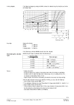
The following sections show how to determine the permissible line length and cross
sections for the various actuators based on examples.
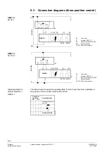
The examples for actuators connected in parallel apply to the following arrangement:
L1
L2
A1
L2
L2
A2
L2
A3
A4
L1
G0
G0
G0
G0
G0
G0
G
G
G
G
G
G
Controller
4
61
4S
0
1e
n
The line resistances of L2 are equal and can be ignored for L1. Separately calculate the
permissible line lengths L2 for other connections (ring, star-like).
6.2 Actuator wiring (three-position)
In three-position actuators, only the situation as presented under
AC 24 V
is important.
Sizing occurs via lines 1 (G), 6 (Y1), and 7 (Y2).
The table shows the main power consumption of an actuator as well as the permissible
voltage drop.
Operating
voltage/pos. signal
Power
consumption
Perm. voltage drop for line
1 (G), 6 (Y1), 7 (Y2)
AC 24 V
3.5 VA
Χ
U/U = max. 8 % (4 % each per line)
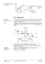
The diagram shows the currents in the connecting lines for
one actuator
.
4
62
1
G
0
6
M
AC 24 V
AC 0,15 A
G
Y1
Y2
GEB13...
1
7
6
0 V
0 V
Determining the line lengths for two actuators GEB13..1 and AC 24 V supply.
Only the currents in line 1 (G) and 6 (Y1) or 7 (Y2) determine the line sizing.
Max. permissible voltage drop =
4% per line
(total 8 %).
∂
Consumption = 2 x 3.5 VA = 7 VA.
∂
Line current = 2 x 0.15 A = 0.3 A.
Max. permissible single line length: 280 m at 1.5 mm
2
line cross section.
Line length for actuators
connected in parallel
Assumption
Actuators with three-
position control
GEB13..1
Power consumption and
perm. voltage drop with
one actuator
P&I diagram:
Conduction currents at
AC 24 V
Example:
Parallel connection of two
actuators

