11/44
Siemens
Technische Grundlagen: Drehantriebe GEB...1
CM2Z4621en
Building Technologies
2017-05-26
This cover protects the DIL switch against dust and water spray.
The HMI of networked types consists of a push button and an LED to allow certain
interactions with the actuator or to provide visible feedback from the actuator.
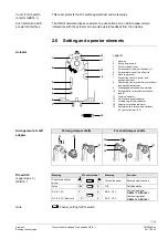
2.6 Setting and operator elements
7
6
5
4
3
2
1
12
11
10
9
8
15
4
62
1Z
1
3
90°
45
°
Legend
1 Housing
2 Rotary angle
scale
3
DIL switch and cover
4
Potentiometer to adjust the span
Χ
U
5
Potentiometer to set the offset Uo
6 Mounting
bracket
7
Connecting cable for power and
positioning signal
8
Connecting cable for auxiliary switches or
feedback potentiometer
9
Disengagement button for gear train
10 Setting shafts for auxiliary switches A
and B
11 Position indicator
12 Self-centering shaft adapter
13 Locking ring for shaft adapter
14 Adapter for position indicator
15 Adjustment tool for auxiliary switches
(10), potentiometer (4, 5)
For long damper shafts
For short damper shafts
46
2
1Z
30
9 0°
4
5°
13
12
9 0°
45
°
46
2
1Z
33
11
9 0°
4
5°
46
21
Z3
2
13
12
14
9 0°
45
°
46
2
1Z
33
11
Meaning
DIL switch label
Meaning
Function
Counter-clockwise
arrow
Clockwise arrow
Rotary angle direction
Active
0
Off
Self-adaptation
DC 2...10 V
2...
0...
DC 0...10 V
Positioning signal
GEB161.1, GEB166.1
DC 0...35 V (
C
omfort)
C
0
DC 0...10 V
Positioning signal
GEB163.1, GEB164.1
Factory setting for DIL switch.
Cover for DIL switch
(only for GEB16..1)
Push button and LED
at external Interface
Actuator
Arrangement of shaft
adapter
DIL switch
(Legend pos. 3)
GEB16..1
Note

