Siemens FDCW221 Скачать руководство пользователя страница 2

en


Installation


FDCW221 
Radio gateway 

Intended use 

The radio gateway serves as an interface between the 
radio detectors (DOW1171, SMF6120) and the FDnet. It 
can communicate with up to 30 addressed radio detectors.
The radio gateway establishes bidirectional radio com-
munication with the radio detectors; the antenna is 
integrated in the radio gateway. The radio gateway 
consists of the following components: 
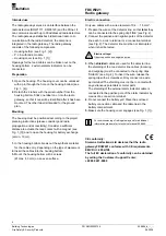
–  Housing bottom (see Fig. 1, [2]) 
–  P.c.b. with radio module 
–  Housing cover (see Fig. 1, [1]) 
Openings for the feed cables can be broken out on the 
housing bottom. 2 external alarm indicators can be 
connected. 

Preparation 

1. 

Open the housing. The housing cover can be unlocked 
with a pin through the hole on the housing bottom (see 
Fig. 1, [4]). 

2. 

Detach the 2 labels with the serial number from the 
housing bottom. Stick one label on or into the radio 
gateway, so that it can still be identified after it has been 
mounted. The other label is intended for the ground 
plan. 

Mounting 

The housing must be positioned according to the project 
planning instructions (please consider good radio 
propagation and accessibility). Consider a sufficient 
distance to actuate the reed contact with a magnet (see 
Fig. 1, [3]) and to open the housing for battery exchange 
(at min. 10 cm). 
 

1. 

In the housing bottom, break out the synthetic material 
for the cable entry, depending on the type of placement.

2. 

Insert the cables into the housing bottom. 

3. 

Mount the housing bottom with 2 screws 
(Ø max. 4.3 mm) on an even surface. 


Electric connection 

Only use cables with a wire diameter of 0.2 … 1.5 mm². 

1. 

Prepare the wires of the detector line; so that 

later

 they 

can be connected to the spring clip 'LINE' (see Fig. 2). 

2. 

Connect the positive and negative poles of the detector 
line each to a micro terminal or a connection terminal 
(see Fig. 2). The detector line must be not interrupted 
when it shall be tested. 


Electric voltage! 

Observe positive and negative poles 


3. 

When 

shielded

 cables are used for the detector line, 

the shielding of the two detector line cables (incoming 
and outgoing) must be connected to the spring clips 
'SHIELD' (see Fig. 2). To insert the wire, release the 
spring clip with a screwdriver. Only connect one wire 
per terminal! The shielding must not be in contact with 
any extraneous potentials or metal parts. 
The shielding of the external alarm indicator cable is 
connected to the positive pole of the alarm indicator by 
means of a connection terminal. 

4. 

Do not connect the battery yet! Place the enclosed 
battery connection cable and the cable ties in the 
battery compartment. 

5. 

Make sure the housing cover engages (see Fig. 1, [1]). 


For commissioning of radio gateway and for additional 
information please refer to technical manual 009865. 


CE conformity:


Siemens Switzerland Ltd declares that the radio 
gateway FDCW221 conforms with CE requirements. 
EMC Dir = 2004/108 
The full EC declaration of conformity can be obtained 
by calling the Customer Support Center: 
+49 89 9221-8000


Building Technologies


PN A5Q00020756 

009866_d_--_--

Fire Safety & Security Products 


08.2008


Содержание FDCW221

Страница 1: ...ntage Montaje Montaggio 1 2 3 4 Fig 1 LINE _ _ _ LINE LINE _ _ _ 1 2 Fig 2 en de fr es it 1 Alarm indicator Alarmindikator Indicateur d alarme Indicador de alarma Indicatore di allarme 2 Connection for test of detector line Verbindung für Test der Melderlinie Liaison pour test de la ligne de détection Conexión para probar la línea de detectores Collegamento per il test della linea di rivelazione ...

Страница 2: ...t the housing bottom with 2 screws Ø max 4 3 mm on an even surface Electric connection Only use cables with a wire diameter of 0 2 1 5 mm 1 Prepare the wires of the detector line so that later they can be connected to the spring clip LINE see Fig 2 2 Connect the positive and negative poles of the detector line each to a micro terminal or a connection terminal see Fig 2 The detector line must be no...

Страница 3: ...den mit 2 Schrauben Ø max 4 3 mm auf einer planen Oberfläche Elektrischer Anschluss Verwenden Sie nur Kabel mit einem Drahtquerschnitt von 0 2 1 5 mm 1 Bereiten Sie die Drähte der Melderlinie so vor damit sie später an der Federklemme LINE angeschlossen werden können siehe Fig 2 2 Verbinden Sie die Pluspole und die Minuspole der Melderlinie mit je einer Mikroklemme oder einer Verbindungsklemme sie...

Страница 4: ...oduisez les câbles dans le fond du boîtier 3 Montez le fond du boîtier à l aide de 2 vis Ø max 4 3 mm sur une surface plane Raccordement électrique Utilisez uniquement des câbles d un diamètre de 0 2 1 5 mm 1 Préparez les câbles de la ligne de détection de façon à pouvoir les raccorder ultérieurement au clip à ressort LINE voir Fig 2 2 Reliez les pôles plus et les pôles moins de la ligne de détect...

Страница 5: ...los cables en el fondo de la carcasa 3 Monte el fondo de la carcasa con 2 tornillos Ø máx 4 3 mm sobre una superficie plana Conexión eléctrica Utilice únicamente cables con un diámetro de hilo de 0 2 1 5 mm 1 Prepare los hilos de la línea de detectores de modo que posteriormente puedan conectarse al terminal de resorte LINE ver Fig 2 2 Conecte los polos positivos y los negativos de la línea de det...

Страница 6: ...el contenitore con 2 viti Ø max 4 3 mm su una superficie piana Collegamento elettrico Utilizzate esclusivamente cavi con diametro di 0 2 1 5 mm 1 Preparate i fili della linea di rivelazione in modo che in un momento successivo possano essere collegati alla clip a molla LINE si veda la Fig 2 2 Collegate i poli positivi e i poli negativi della linea di rivelazione rispettivamente con un micromorsett...

Страница 7: ...7 Building Technologies PN A5Q00020756 009866_d_ _ Fire Safety Security Products 08 2008 ...

Страница 8: ...mm de Bestellangaben 9V Lithium Batterie A5Q00004142 9V Lithium Batterie DBZ1190 AA 4677080001 Mikroklemme 0 28 0 5 mm DBZ1190 AB 4942340001 Verbindungsklemme 1 2 5 mm fr Détails pour passer commande Pile 9V au lithium A5Q00004142 Pile 9 V au lithium DBZ1190 AA 4677080001 Microbornier 0 28 0 5 mm DBZ1190 AB 4942340001 Bornier 1 2 5 mm es Datos de pedido Batería de litio de 9 V A5Q00004142 Batería ...

Отзывы: